
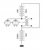
No, it isn't elegant at all. The small impedance of the 90 V battery shunts the OT's primary. As KeesB says, a high impedance CCS is mandatory.
Best regards!
Best regards!
A pentode is just a better current source, that's all. And because you have everything already available to test it as well .... unless you are totally satisfied of course. Do you have a picture of this amp? How much power do you get from it?
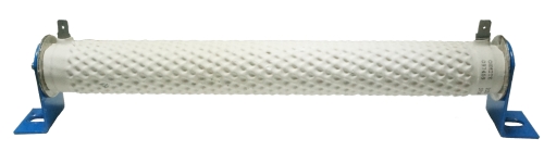
An ordinary resistor comsumes some part of the AF output power.Maybe I'm missing something... What's the advantage over using a resistor? Ignore the header...
Best regards!
A tube is made to get hot, not so a resistor ;-)
Horseschitt. That's how they work. They turn power into heat!
True though that a resistor would consume some of the audio, but what about a CCS made from an LM317 and a MOSFET? Or just a pentode with a grounded grid? Then you could drive said grid to have a SE/PP switchable amp?
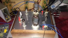
To answer a few questions: Lampie- I haven't tested it but compared to other amps I have I think at least 20w. I have no pictures of the amps. Disco: the powersupply shorts the signal;Kodabmx: using a ccs this way only half the primary is used; besides you waste a lot of energy because the amp is working at 1000v, 0,1A that's 100watts. My floating 519 consumes only 9 watts and the whole primary is used for the signal.
It is possible to use a P-P OPT for SE by CCS loading the half not used by the output tube. I have done this by building a big CCS with an IXYS 10M45 under the cathode of a fat sweep tube. It works, sucks up a lot of power supply and turns it into heat, but that's not the real problem.
By using a half of a P-P opt, you get 1/4 of its rated impedance. The "normal" load for a VT4C / 211 is about 10K ohms. Two in parallel would need about 5K, so in this case you would need a 20K ohm OPT capable of eating 100 mA or so and reproducing the full audio band with good fidelity.....not exactly common.
This looks like an elegant solution that deserves some more experimentation, especially now that I have my UNSET amp breadboard running and it seems to want about a 3K ohm SE OPT capable of eating 30 to 40 watts and running on about 650 volts.
Transformerless output.Ahh yes the holy grail.Carry on one day perhaps.Until then tube fans
will just have to live with the evil o/p transformer.
will just have to live with the evil o/p transformer.
There are many ways to create great amps, all depends on the choice of loudspeakers. OTL amps are not always the correct choice. But these can create magic with the right speakers. I have build OTL’s for more then 30 years now but will now only build Zotl’s or HV OTL’s to drive ESL’s directly. For me the last is the ultimate match. Nothing sounds more natural then a direct driven ESL ( that is my opinion). Zotl is coming very close on dynamic loudspeakers. It can not be explained in words but needs to be experienced.
As I said before the drawbacks of using half the primary of a PP OT are not using the full potential of the OT and the high dissipation of the ccs ( this being a tube or some solid state thing) which is equal to that of the class A tube that processes the signal. My idea was that many people have some PP OT that could be used as a SE OT in a way that hasn't been done before that the cost of the floating circuit I have proposed is relatively modest. Besides it's flexible: it can be used both in high and in low voltage circuits. Then if you really like what you hear you can decide to buy a big OT (or leave it as it is) or, if you don't just dismantle it but then it hasn't cost you much.
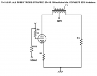
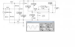
At first glance today this looks like a rather unlikely hookup. But it can be separated into its parts. The RHS is a half-wave voltage tripler, so the current in the HV Power Transformer has a large DC component. That could be avoided by using a higher voltage & a full or half wave doubler, take your pick. FWD better, the ripple is at twice the line frequency.
That with the 40GK6 forms a programmable CC source. The DC current due to the 2X VT4C is cancelled by the DC current due to the CC supply formed by the 40GK6 & the floating 910V PS. The limit of output power from the VT4Cs is set by the AC tolerance of the CC supply.
Consulting the curves for the VT4C it look like on a 1000V supply a pair of VT4Cs could easily swing 1600V P-P. With no signal all appears to be OK. The DC current in the OPT is essentially Zero. But with a 40Vrms (56V Peak) input it looks like there is a problem. The VT4C/GL211 data sheet shews 24 Watts should be available for a pair of tubes on 1000V PS running parallel. The indicated output is close to that. But there is distortion.🙁
An earlier suggestion of parallel feed seems like a simpler solution. Would I use this circuit? Probably not. Much easier to simpler get the correct OPT. But an interesting diversion, anyway. Thinking outside the box always worthwhile.🙂
Attachments

The VT4C/GL211 data sheet shews 24 Watts should be available for a pair of tubes
I have an amp that I built about 14 years ago. It uses 211's or 845's. Each channel uses a single tube into a 10K SE OPT on 1050 volts. I run old tubes at 70 mA max, but have cranked some Chinese tubes up to 100+ mA without issue. Power output doesn't change much, but the damping factor does. This is important with the 211 / VT4C due to its higher Rp than the 845.
It makes about 22 watts per channel before entering A2 and nearly 40 watts in A2.
I haven't tested it but compared to other amps I have I think at least 20w.
More correctly, it has an output of (ideally) .61 Watts, then a large glitch on half of the waveform, as the CCS squashes down to zero Volts and is then reverse voltaged.
All good fortune,
Chris
- Status
- Not open for further replies.
- Home
- Amplifiers
- Tubes / Valves
- Simple tube circuit transforming push-pull output transformer into single ended one