Lampie519,
I am not sure what you said in post # 120. But I think you meant:
Apply B+ to the center tap. Connect the first VT4 plate to one end of the primary. Apply the driver signal to that VT4 grid. Connect the second VT4 to the other end of the primary, but do not apply any signal to the grid (that tube becomes the current balancer). Use the equal DC quiescent currents to balance the fields. That does sort of become a "single ended circuit" in that only one side is driven.
Be sure you do not bypass the second VT4's self bias resistor, that will raise its rp a little. The second VT4's will still become a very poor current source, and will put a heavy load on the first VT4's plate (through the mutual coupling of the primary halves).
I say if you do it that way, instead try using a pentode or beam power tube instead of the second VT4. Same current and voltage in the pentode/beam power tube (as the second VT4 would have been), with higher rp, so more SE power out. But with a VT4 as the driven tube, you need a high-power high-voltage pentode/beam power tube for the current balancing stage. Try an 813 for example.
Last edited:
Yes, all is true! Just as already 2 VT4 tubes are availabe in that amp it is easy to try this ( just a few wire changes). As also a PL519 is available both options are possible and 1 VT4 can be saved for later when needed.
I never had enough parts and energy to use a VT4. But if I did, it would be an 845 instead.
And the first thing I would do for either, is build a 10V 3.25A DC filament supply.
And the first thing I would do for either, is build a 10V 3.25A DC filament supply.
I have build a RF PSU for the heaters (small and no capacitors or regulators). Why a 845 instead? Are these not interchangeable?
My guess is that these types where on hand (like in all of my projects, i choose the tube i have in house) As i have thousand's of tubes lying around waiting to be used, why should i buy more just because it "could" be a better choice? Yes, there are better tubes (and there will always be) to choose from when you start from scratch and have no tubes collecting dust.
The most fun part of this hobby is to use what is at hand and build a most beautiful amp you can with these, don't you think so either?
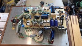
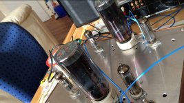
Attachments

Last edited:
Thanks for the compliment Lampie. Of course I knew my "solution"would cause some frowns. But after all it has led to expert comments leading to better options like the extra secundary winding and as proposed by myself using the 0-4 ohms part of the secundary of the OT and applying a ccs there. One thing should be kept in mind. If the max ac-voltage across the OT would 1000v and the turn ratio is 25:1 then 40v ac can appear on the 4 ohms taps which means the ccs must be able to handle that voltage, besides having to dissipate as much as the power tubes do.
Now regarding the "passive" vt4 solution. I have tried that as this is the first thing you think of although not with VT4's. The reason I didn't do it with the VT4 was (with my 6k6 OT) using one half of the primary results in a impedance of a quarter of 6k6 = 1k65 which a gross mismatch for a single VT4. Hence parallelling the VT4's (10k becomes 5k) and adding a circuit that would cancel the magnitizing current. I had not realized all the requirments for the ccs and especially the effect of the possible large ac voltages produced by the powertubes. I was lucky not having blown up the ccs but that might have happened.
Like 6A3s I also prefer the 845 which is a fantastic sounding tube but I had this pp VT4 amplifier at hand that I wasn't happy with and so the idea came up to change it into a SE.
Of course you might build a lower power version like 2A3 or 300B but that would be sensible only if you would happen to have some pp outputs at hand, some power transformer, etc. otherwise the cost of the ccs would outweigh the price of a SE transformer or even more. That wouldn't make sense. So all I can hope for you find a destination for some unused materials in a maybe unconventional way .
That is the most fun, trying to fit something with components that actually do not fit at all and get it working with good results ! We get positively surprised sometimes of the outcome (not always though haha, if the amp communicates with you using smoke signals instead of sine waves). But in any case we can all learn from it when sharing it here!
- Status
- Not open for further replies.