It works regardless of feedback. I personally dislike trickeries like bootstrapping.
You could consider referring the emitter resistors of the input stage to ground.
Hello,
in this case there would be no more css ?
how would you add a buffer ?
connected to floating or regulated power supply?
yamaha use N channel drain output with a buffer, maybe we should do the same
thanks
Last edited:
Thank you
But I need single inp to symmetric out and usg is symmetric to symmetric

There would be no CCS, but well-defined references. Your circuit is complete, no need for a buffer. JFET input would be better. BC560C is scanty. Could you accept a common supply voltage lower than 35 V?
I already have transformers for the ouput stage, but we could use lower for the input and vas.
but I want to see your idea with JFet
but I want to see your idea with JFet
On the other hand if we continue with Jfet we will have to go on another topic, I posted here because the amp was similar to the VSSA
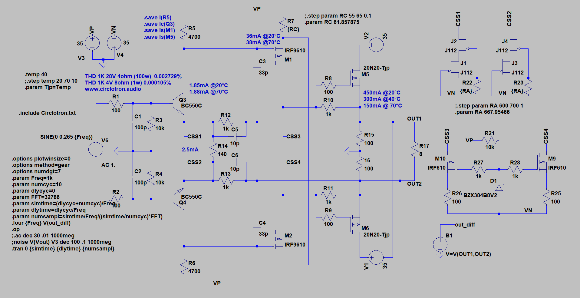
VSSA Circlotron
VSSA Circlotron
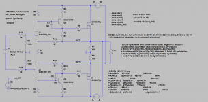
We are nearly there, except two source resistors going to ground in the place of R3.
Complications: JFETs should be operated at low drain-source voltage. You would need four matched pieces of 2SK170BL, a bipolar cascode and two extra resistors.
The 2SK170BL and 2SA1381 are fine.
Complications: JFETs should be operated at low drain-source voltage. You would need four matched pieces of 2SK170BL, a bipolar cascode and two extra resistors.
The 2SK170BL and 2SA1381 are fine.
SSA standard 😉
Hi Andrej, i just sim this amplifier and I found 5mA on input, 40mA on vas and 400mA output with 11mA on CCS >> CFA_EVO.asc
that's right ? it seems a lot compared to usual VSSA (2.4mA / 10mA)
https://www.diyaudio.com/forums/att...le-symetrical-amplifier-ssa-power-amp-1-7-pdf
I am interested in this scheme for my circlotron, I do not know if I have to use a differential current feedback or yours with one or two capacitors for more stability
Circlotron Audio
thanks
Best regard
Sébastien
Attachments
Last edited:
Hi ultimate86
Your VAS current needs to be higher because of mosfet use. The mosfet is highly non linear at low current. Use of higher bias current for output is the designer choice. Personally I target higher mosfet output current to be in class A at higher power level. For input current you want to limit the power dissipation otherwise you will need higher power transistor type normally with lower HFE than low power type.
Fab
HI fab,
yes I know that mosfet need more current to be linear but in fact I'm just surprised to see 40mA on KSA1381/KCS3503 VAS in last andrej schematic (and 5mA on input)
I was also interested in the single-capacitor feedback that we see in this last scheme that has less low-frequency distortion
yes I know that mosfet need more current to be linear but in fact I'm just surprised to see 40mA on KSA1381/KCS3503 VAS in last andrej schematic (and 5mA on input)
I was also interested in the single-capacitor feedback that we see in this last scheme that has less low-frequency distortion
Last edited:
- Status
- Not open for further replies.
- Home
- Amplifiers
- Solid State
- Simple Symetrical Amplifier