This could be a suggestion....🙂
Very very close to the circuit of my Mirand A1 V1.1!?!!
Very very close to the circuit of my Mirand A1 V1.1!?!!
I thought you work together.
 😀
😀MiiB is fast hehe, I'm sure he's up to something or just experienced the sound of SSA. 😎
It would be really nice to see the whole sch.
It would be really nice to see the whole sch.
We are two different types of engineers.
We have both been listening to it. Ask him what he thinks! 😀
We have both been listening to it. Ask him what he thinks! 😀
I think the basic topology is tremendous. You have attacked the output in a unique manner..where you aim to remove the P to N differences. I have fitted a current dumping error correction circuit on the version I have built. which by the way sounds rather ok...
Now to the house keeping. I do believe that the weakest part of this fine circuit and the very reason why it does not simulate particularly well is the poor relations between the impedance of the current drive and the feedback currents. The basic amp is basically fed from a 1Kohm current source..which is way too low to prevent the feedback currents from modulating the drive-current. This is the main source of error in the circuit and by fitting high (very high) impedance current-sources specs are terrific. I will not show my housekeeping here....But I'am quite sure you catch the direction.
Now to the house keeping. I do believe that the weakest part of this fine circuit and the very reason why it does not simulate particularly well is the poor relations between the impedance of the current drive and the feedback currents. The basic amp is basically fed from a 1Kohm current source..which is way too low to prevent the feedback currents from modulating the drive-current. This is the main source of error in the circuit and by fitting high (very high) impedance current-sources specs are terrific. I will not show my housekeeping here....But I'am quite sure you catch the direction.
We are two different types of engineers.
We have both been listening to it. Ask him what he thinks! 😀
OK 😉, MiiB what's your opinion regarding SSA sound? What was the sch you'd experienced? 🙄
Last edited:
By the way. Good you replaced the zeners by LM431!!! The Zeners mess things up!
Yeah, I knew that from begining, TL431 makes much more stable current supply to the bridge, unaffecting the fixed cascodes base potential, still current sources puts relations to another level. OK, tracking cascodes at input and VAS again another story, so all together combined I'm not surprised it is tremendous. 😎
Sound? 🙄
The use of tracking cascode should be done with care as i have seen oscillations just above or in conjuction with 180 degree phase shift.
But if remember right, then there is a lot of measurements/simulation of different type of VAS stage floating around in here done by a french guy 7 - 8 years ago.
But if remember right, then there is a lot of measurements/simulation of different type of VAS stage floating around in here done by a french guy 7 - 8 years ago.
The use of tracking cascode should be done with care as i have seen oscillations just above or in conjuction with 180 degree phase shift.
But if remember right, then there is a lot of measurements/simulation of different type of VAS stage floating around in here done by a french guy 7 - 8 years ago.
Peufeu memory distortion plus magic resistor? 😉
Just to show the difference.
OMG these two convinced me, again some work ahead hehe

I think it was him, but there is a lot more.
1) phasemargin
2) and gain in the vas stage / or impedance.
The first pic if a copy of Marantz HDAM buffer and the second is a slightly modified, more standard diamond buffer.
But i would allways add a little series resistor to prevent oscillations in real world, also on mosfets.
But i would allways add a little series resistor to prevent oscillations in real world, also on mosfets.
Sims are very useful tool to avoid-eliminate major flaws and helps converging to the best solution by optimizing/correcting the parameters. Still the basic ideas of topology and solution is up to a designer. In reality all well designed circuits has to be tested throughout especially on stability issues, since these are parts-layout dependable. And if you go to tracking cascodes, current sources ie. high impedance local circuits in a big scale, where oscillations and instability are just around the corner, than a designer must really have a good knowledge and a lot of practical experiences. 🙂
Sometimes practical results (measurements & sound) are better without them. 😉
But i would allways add a little series resistor to prevent oscillations in real world, also on mosfets.
Sometimes practical results (measurements & sound) are better without them. 😉
Last edited:
Now to the house keeping. I do believe that the weakest part of this fine circuit and the very reason why it does not simulate particularly well is the poor relations between the impedance of the current drive and the feedback currents. The basic amp is basically fed from a 1Kohm current source..which is way too low to prevent the feedback currents from modulating the drive-current.
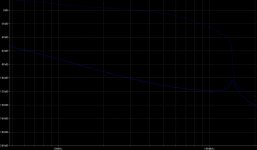
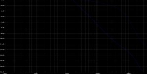
Spectral analyzer shows incredibly linear and even response in spectral distribution up to 100 MHz region. Increasing the amplitude of the base signal enlarge the amplitude of all spectral lines in a linear manner, there's no step amplitude response between first few and damping of the others, like it should be. So the 1 k resistor is doing it properly, allowing the drive-supply current (which by definition should be constant) to be modulated by FB current in a very frequency-linear manner. So nothing to blame to resistor, it's doing its job just perfectly. 😀
This is the main source of error in the circuit and by fitting high (very high) impedance current-sources specs are terrific. I will not show my housekeeping here....But I'am quite sure you catch the direction.
Achieving high impedance current supply by cascoded CCS is not a problem, we also had CCS in the SSA sch long time ago although more or less because of their constant part of equation. OK, I have 14 V potential gap, very constant and clear TL431 power supplies and two twin parts space on PCB for each C-CCS, so all supporting role actors are there. Terrific specs are motivation, sound results end goal, will do the homework. 😉
So the 1 k resistor is doing it properly, allowing the drive-supply current (which by definition should be constant) to be modulated by FB current in a very frequency-linear manner.
It's not...Higher impedance M-Ohm would make it so...ideal CCS better option. difference is like bouncing a ball on a soft wooden floor and on solid concrete. One rattles the building and is felt everywhere. Both floors bounces the ball one just bounces the ball better..🙂
Last edited:
- Status
- Not open for further replies.
- Home
- Amplifiers
- Solid State
- Simple Symetrical Amplifier