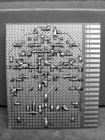
Orangebelt design halfway done; dedicated to bigun, the blackbelt designer amongst us.
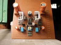
Zeners will be added later. I want to test it without them. I am expecting a kaboom. Pray for me brothers, as this is my very first symmetrical work.
I'll post amp behaviour soon, whether smooth or erratic. I'm not afraid, I know I have many saviors here.
Zeners will be added later. I want to test it without them. I am expecting a kaboom. Pray for me brothers, as this is my very first symmetrical work.
I'll post amp behaviour soon, whether smooth or erratic. I'm not afraid, I know I have many saviors here.
Attachments
I am eager to start as soon as possible !
Can i replace 2sk 1058 and 2sj 162 with IRFP240 and IRFP 9240 ?
kp93300
Sorry KP93300, no you cannot.
Nico
"A little help from my friends"
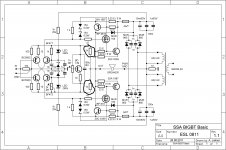
I had the idea to modify one of my good existing amplifier to current feedback and symmetric input.
Comments will be appreciated as i don't feel comfortable with my feedback design:
R18; R17, R15, R16
Only half (positive side) of the schematic shown.
I had the idea to modify one of my good existing amplifier to current feedback and symmetric input.
Comments will be appreciated as i don't feel comfortable with my feedback design:
R18; R17, R15, R16
Only half (positive side) of the schematic shown.
Attachments
By habit, and if the printed board is ok, CF is rock stable at all gains. The only issue reducing feedback can be a decrease of damping factor and slight augmentation of THD, OMHO.I haw increase the gain of BIGBT by increasing this resistors to 2.7K (28dB) is that OK, and will there be any issues about instability etc…
You are right, input level has to be 1V for full power output.
Don't know if this old Sansui patent is applicable/desirable.
When the transistors Q1, 5 are conductive, the current flowing to Q1 flows through the capacitor 10, Q5 as well as the constant current circuit 3. The current also flows in Q4 through the capacitor 10 when Q2, 4 are conductive similarly. This current flows only at transient time until the capacitor 10 saturates. Accordingly, this circuit allows the current exceeding that limited with the constant current circuits 3 and 6. Greater current depending on greater input signal can be flowed, allowing to extend the dynamic range.
Attachments
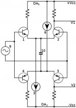
I wonder why there is so many owfull patents on the market ! This will produce an overshoot, then IM, and non linear response if the cap is little, and nothing more than increasing the current ( that you can do in a linear way by design ), if large.Don't know if this old Sansui patent is applicable/desirable.
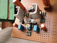
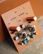
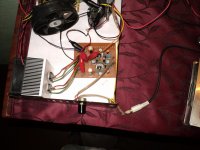
Board connections done. Added 1K pots in parallel with 100ohm resistors for fine tuning offset, after basic setting with 20K.
Going to fire it within an hour. Right now going to market to buy vegeatables - order from higher authority.
Very excited.
Going to fire it within an hour. Right now going to market to buy vegeatables - order from higher authority.
Very excited.
Attachments
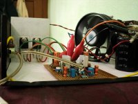
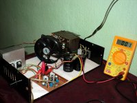
Initial test done.
Settings:
Bias 100mA total. Offset +-5mV(varies all the time). 100ohm gate stopper at board and FET. No source resistors added. Supply +-20V, 15000uFx2 smoothing caps.
Observations:
Stable bias. No oscillation(well, I don't have a o-scope, but my am receiver is very efficient in this job LOL, plus no overheating anywhere, the input BJTs are warm, the VAS BJTs are little more warmer, thats all and thats what I expected.) Offset isn't very "stable" but is limited to +-5mV, also is easily to set by the 1K pots after setting close to + or - 1volts with the 20K pot. NO audible noise with inputs open.
Currently playing The Look Of Love - Saskia Bruin
😱
Attachments

Last edited:
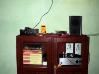
Thanks everyone who helped me with this amplifier, I got another masterpiece on veroboard, without you guys it wasn't possible.
I had the idea to modify one of my good existing amplifier to current feedback and symmetric input.
Comments will be appreciated as i don't feel comfortable with my feedback design:
R18; R17, R15, R16
Only half (positive side) of the schematic shown.
Esperado you've been attracted to this thread for some reason but was really not aware why at begining.
Your sch is classical example of people ingenuity to make progress on certain ideas. The SSA principle is very flexible and I can see how to implement it in your case turning the amp to current feedback SSA type.
Just remove R15-R18, D8,D9, split fedback loop like in SSA design (two times two feedback resistors) connect it to the emmiters resistors of input differential pairs, also lower 150 ohm resistors to 10 ohm. Leave the current sources Q3/Q9 like they are and because of cca. 1,2V DC potential between +/- diff-pair emmiter resistors you have to filter AC out with a good 100uF elco as much as possible.
Now you have your amp being SSA pimped. 😀
Impressions about sound?
Alive. One word is enough.
Well, mid bass to treble is perfect. Very good tonal balance, independent of volume; this I liked the most. A very transperarent sounding machine. I have yet to test the bass response as currently I lack a passive Sub.
I'll update transient production quality later; I think this needs more time than usual.
Cheers.
Last edited:
Thanks everyone who helped me with this amplifier, I got another masterpiece on veroboard, without you guys it wasn't possible.
It started ...

You happy - me happy. Congratulations. 😉
P.S. Now you can start to think to go SSA way - emmiter bias arrangement - it will give you even more stable DC conditions and less parts count. 🙂
It started ...
You happy - me happy. Congratulations. 😉
P.S. Now you can start to think to go SSA way - emmiter bias arrangement - it will give you even more stable DC conditions and less parts count. 🙂
I'm already on it; my next project.
Special thanks to you.
I'm already on it; my next project.
Special thanks to you.
Thank You. 😉
nope - the issue is always one of moderation. I like to see that I have the option to dial in some H2 should I want it because of the desirability that has been reported for amplifiers with a 'hiraga' like monotonically decreasing profile of harmonics. Only a small amount of H2 is warranted.
I think we share some common approaches to our amplifiers. My first CFB amp was inspired by JLH designs. I'm curious about your VAS feedback because the CFB amp has a relatively low impedance feedback node which means you can load down the VAS too much of not careful - and so I see why you need a CFP VAS. I am thinking instead that I can take some nested feedback from the CFP driver stage if I want to reduce the nfb factor around the output stage and I plan to allow for this option on my pcb design.
My own simulations show dominant H3, or at most equal H2/H3 with the all BJT version - which I don't find surprising given it's symmetry.
Hi Bigun, start a TGM5 thread. If your going to design a PCB for this Ill have a go at it. I hate doing PCBs, no patience or time for it and so I have them designed and completly built up including components by pro companies that charge for it but for a once off amp it isnt viable.
I might not entirely end up exactly as your design is but a couple of wires or components off or below a PCB doesnt bother me.
My old design is a class A heater, with 4 pairs good old 2sj50 2sk135 in a cfp arangement as advocated by JLH at the time. Ill have to take it apart to get the exact schematic again, Ive forgotten what I did. I had some input given by JLH himself via my varsity prof and the idea was a amp with very low high order harmonics. It must have sounded pretty good otherwise I would have taken it apart or thrown it away but its still in my garage under a tarpole with all my other succesfull and potencially good sounding amp endevours.
I know why ;-) I'm dedicated at CF from years now, using it exclusively as far as audio is in concern. And your design is f... brilliant. As brilliant as your kindness is touching.Esperado you've been attracted to this thread for some reason but was really not aware why at begining.
I was away from electronic since 25years, and it is hard for me, now, i don't feel any more the things, obliged to make calculations for everything, age is a nightmare, too.
That was my purpose, before to build from scratch YOUR definitive prototype.The SSA principle is very flexible and I can see how to implement it in your case turning the amp to current feedback SSA type.
See attachment, that's what you means ? I just wonder why you want me to change the emitter values from 150 ohms to 10, it increase current and open loop gain, right ? it need 4watts for the 330 ohms then, and, if i'm correct, the gain will be 33 if 330ohms are set to 660 now ?.Just remove R15-R18, D8,D9, also lower 150 ohm resistors to 10 ohm. ...because of cca. 1,2V DC potential between +/- diff-pair emmiter resistors you have to filter AC out with a good 100uF elco as much as possible.
Where did you see this 100µF, where i have put the 1000µ ?
I'm lurning LT spice, right now, and it don't want to pimp-itNow you have your amp being SSA pimped. 😀

But, when it will go, i think we'll have all the inputs architectures, now ? This one is complementary from the Shaan one. (Congratulations, Shaan)
Attachments
Last edited:
- Status
- Not open for further replies.
- Home
- Amplifiers
- Solid State
- Simple Symetrical Amplifier