...I choose IRFP240 dan IRFP9240 because I have the models 😀
What are your models?
Best wishes
David
Hi Valery
These are level 1 models. Unfortunately they are useless for distortion simulation unless Multisim has some tricks I don't know about.
I have often seen people use a level 1 model and produce unrealistic distortion simulations and I suspected Bimo may have been mislead, hence my question.
One more reason for you to move to LTSpice, the MOS models are better.
Best wishes
David
Emmm... thank you for letting me know - I actually did not pay attention to this...
However, live prototype measurements are pretty much inline with what I see on the Multisim THD meter. Maybe there is some trick there...
I'm getting familiar with LTSpice - not as fast as I'd like to... still need to learn some concepts there 🙂
Cheers,
Valery
However, live prototype measurements are pretty much inline with what I see on the Multisim THD meter. Maybe there is some trick there...
I'm getting familiar with LTSpice - not as fast as I'd like to... still need to learn some concepts there 🙂
Cheers,
Valery
However, live prototype measurements are pretty much inline with what I see on the Multisim THD meter. Maybe there is some trick there...
If the FET is not a major contributor to distortion then it will not make much difference of course. The FET driver is buffered and that may explain your results.
But it becomes crucial when the output transistors are FETs.
...with LTSpice - not as fast as I'd like to... still need to learn some concepts there
I don't find it very intuitive, perhaps I don't understand some concepts either.
But still fairly impressive.
Best wishes
David
Hi Valery
These are level 1 models. Unfortunately they are useless for distortion simulation unless Multisim has some tricks I don't know about.
I have often seen people use a level 1 model and produce unrealistic distortion simulations and I suspected Bimo may have been mislead, hence my question.
One more reason for you to move to LTSpice, the MOS models are better.
Best wishes
David
Multisim model give slightly better THD than LTspice model.
This is my LTspice model:
.model irfp240C VDMOS(nchan Vto=4.0 Kp=4.8 Lambda=0.0032 Rs=0.01 Rd=0.1 Rds=1e7 Cgdmax=2600p Cgdmin=10p a=0.35 Cgs=1250p Cjo=3000p m=0.75 VJ=2.5 IS=4.0E-06 N=2.4)
.model irfp9240C VDMOS(pchan Vto=-3.76 Kp=9 Lambda=0.004 Rs=0.064 Rd=0.1 Rds=1e7 Cgdmax=1200p Cgdmin=15p a=0.26 Cgs=1130p Cjo=2070p m=0.68 VJ=2.5 IS=4.0E-06 N=2.4)
... better THD than LTspice model.
Hi Bimo
That is what should be expected.
In this circuit there is probably not much difference because the crossover distortion is the main factor.
What are the THD results at 20 kHz?
Best wishes
David
Using IRFP THD at 218W/8Ohm, 20kHz -> 0.053580%
Using lateral THD at 218W/8Ohm, 20kHz -> 0.003543%
Using lateral THD at 218W/8Ohm, 20kHz -> 0.003543%
If the FET is not a major contributor to distortion then it will not make much difference of course. The FET driver is buffered and that may explain your results.
But it becomes crucial when the output transistors are FETs.
In fact, I forgot to mention, but I refer to the design with three pairs of IRFP240/9240 at the output 🙂 Well, anyway, I see what you mean - I will look deeper into it...
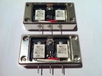
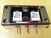
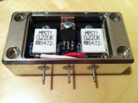
Here are the live measurements:
HEX FET OPS in combination with my hybrid IPS
P.S. I did not re-draw the FETs at the schematic there - they look like BJTs, but they are FETS 😉
HEX FET OPS in combination with my hybrid IPS
P.S. I did not re-draw the FETs at the schematic there - they look like BJTs, but they are FETS 😉
Using IRFP THD at 218W/8Ohm, 20kHz -> 0.053580%
Using lateral THD at 218W/8Ohm, 20kHz -> 0.003543%
This is with the circuit of post #4103 except with an 8 ohm load rather than a Zobel?
Did you try different source impedances?
Some circuits are more sensitive to this than others.
And what lateral models?
Best wishes
David
Last edited:

This is with the circuit of post #4103 except with an 8 ohm load rather than a Zobel?
Did you try different source impedances?
Some circuits are more sensitive to this than others.
And what lateral models?
Best wishes
David
No. This is complete amplifier as I mention in my earlier post. And I add 2,2 ohm base BJT transistor on BIGBT OPS.
The LTSpice models:
.MODEL 2SK1058_D NMOS (VTO=403.969M KP=20U L=2U W=29.7482M GAMMA=0 PHI=600M LAMBDA=184.988F RD=60.8251M CBD=2.56138N IS=10F CGSO=1.13517N CGDO=1.13517N TOX=0 NSUB=0 TPG=1 UO=600 RG=50 RDS=1MEG )
.MODEL 2SJ162_D PMOS (VTO=842.193M KP=20U L=2U W=21.3317M GAMMA=0 PHI=600M LAMBDA=20.7067M RD=837.199M CBD=2.96862N IS=10F CGSO=1.13517N CGDO=1.13517N TOX=0 NSUB=0 TPG=1 UO=600 RG=50 RDS=1MEG )

- Status
- Not open for further replies.
- Home
- Amplifiers
- Solid State
- Simple Symetrical Amplifier