LC, sorry, i am loosing the overview. Anyway, that version i like best so far and the super simple first one. It was inspiring.
LC, sorry, i am loosing the overview.
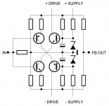
Simple overview: it is all the time just about the symmetrical current feedback loop front end (pic) in all kind of variations.
So far two versions incorporating this topology were actually built and listened to, mine and Nico's. Time will bring out the best from the simple ones. But if someone wants to go to more complex design I would suggest post #205. 😉
Attachments
Nico, could you please post the schematic that you are using right now ? That is the version i like most by intuition.
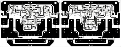
PCB is dual mono
Attachments
Last edited:

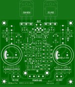
I see 35V 10mF filters on board 1.4. Isn't meant to be 50V? Because ~35VDC is the rails spec, no?
Salas, I used a 22-022V transformer so I only needed 35V caps. You can run this design to 55V if you please and then 63V caps is the obvious choice. My calculation (22VAC - 1.4V)x1.414 plus 10% mains variation = 32V then 35V caps are fine.
Alex's board is nicer looking than mine so uses Alex's board. I just showed what I use for interest sake. My track are fairly narrow and pads are small which is not so great if you are going to etch at home, my PCBs are commercially made.
Alex what Salas said regarding 50/63V caps makes good sense if there are people who want to push the power envelope a little, all I wanted to do was confirm that the amp sounds as good as it is simple. It does.
Nico
Alex what Salas said regarding 50/63V caps makes good sense if there are people who want to push the power envelope a little, all I wanted to do was confirm that the amp sounds as good as it is simple. It does.
Nico
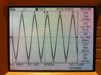
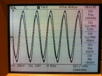
Today I made some measurements with the SSA BIGBT exact sch post #217 🙂
As you can see from the Tex scope plots, CH1 input signal, CH2 output signal:
- first plot, fs = 1 kHz, Av = +21,44 dB, phase shift = 0°
- second plot, fs = 2 MHz, Av = +21,68 dB, phase shift = -24°
I also measured/calculated the output impedance at 1, 10 and 100 kHz, 4 ohm load and it is 180 mohm in all cases, which will also be improved with higher voltage gain in the second stage, later in the process.
So I intend to prepare SSA sch, mosfet driver/BJT output, soon. 😉
P.S. Input signal at 2 MHz is a little bit more rounded than at 1 kHz because of the signal generator upper limit distortion. As you can clearly see on the plots, output signal corectly followed this anomaly. 🙂
In the whole SSA amp there were no compensating capacitors whatsoever, only three electrolytic caps for DC potentials smoothing. 😉
Attachments
Last edited:
18.1V(RMS) into 8,2 OhmsDid you measure the amp's power on some dummy when using the 2x22VAC Tx?
Thanks. That's 40W. Not bad. At what DC bias? The sensitivity is on the low side. Something like 16dB? Would it go much more THD if fixed at say 28dB? Is there enough OLG?
Salas, I adjusted the gain to work with my pre-amp out which is 2V p-p. I have not checked OLG, but the BW is huge so I cannot see a problem increasing gain a tad.
I have not decided what final bias should be, it sounds nice as it is. On the week-end I will set up the spectrum analyser and see what bias offers the best harmonic distribution. Just by listening it is hard/impossible to tell.
I have not decided what final bias should be, it sounds nice as it is. On the week-end I will set up the spectrum analyser and see what bias offers the best harmonic distribution. Just by listening it is hard/impossible to tell.
For the full power measurements I will prepare some 200VA transformer/60mF caps bank running on +/-35V, as specified as Safe Operating Area for one output pair in SSA. 🙂
Until now I have used 1,5A limited power supply for the safety reasons, like always at the begining of any new power amp's life. 😎
I also calculated the propagation delay in the 2 MHz Tek plot from input to output waveform which is exactly 33ns, I suppose due to parasitic capacitances sumed from all semiconductor parts together and current layout (spider network). This figure maybe improved or not with the use of a neat PCB like Alex or Nico made, will find out later. 🙄
P.S. The propagation delay in 1kHz plot is of course the same 33ns, only that it is not visible in 500us/DIV time domain sweep. 🙂
Last edited:
- Status
- Not open for further replies.
- Home
- Amplifiers
- Solid State
- Simple Symetrical Amplifier