Real load, 6 ohm speaker connected, 10/100 kHz square wave, positive edge slew measured. 😉
at less than 1 watt into 6 ohms ?
that tells nothing because at these frequencies the speaker is an inductive load.
Thus almost no current !
Usually such slew rate measure is taken with a capacitive load.
roughly i=du/dt *C assumed c= 10*^-9 F (Asec/V) du/dt you claim 300 V/10^-6sec
yields 300*10^-3 Amps= 300 mA
but ok 100 V/µsec can be achieved. Case settled.
Of course however without gate stopper resistors ....
nevertheless I don't like Fets .
So still asking for ideas how to make a constant bias vs junction temp with only 2 thermal trak diodes?
yields 300*10^-3 Amps= 300 mA
but ok 100 V/µsec can be achieved. Case settled.
Of course however without gate stopper resistors ....
nevertheless I don't like Fets .
So still asking for ideas how to make a constant bias vs junction temp with only 2 thermal trak diodes?
roughly i=du/dt *C assumed c= 10*^-9 F (Asec/V) du/dt you claim 300 V/10^-6sec
yields 300*10^-3 Amps= 300 mA
but ok 100 V/µsec can be achieved. Case settled.
Of course however without gate stopper resistors ....
nevertheless I don't like Fets .
So still asking for ideas how to make a constant bias vs junction temp with only 2 thermal trak diodes?
Read Bob Cordell book.
After 😎
This must be one of the most outstanding design and construction of a DIY effort I have seen on this forum since I registered in 2002, wish I could have something like this even in a more humble appearance.
Guess many of us have learned more than a couple of things following your thread including how to build a home brewed IGTB. Congrats for this great voyage and of course the great amp you built.
Hope there is more.... like a group buy for PCB's?
Cheers, Tony
+10
I've been waiting for a long time, but seem like Andrej is holding the PCB group buy. What's the hold up Andrej? We want to hear your wonderful amp.
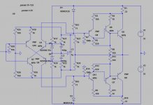
This topology works fantastic in terms of thermal tracking no test of audio qualities yet.
In theory note that it employs current amplification throughout and the power stage is NOT EF .
D1 D2 are the on chip thermal trak diodes Q5 Q8 are thermal trak BJTs.
In theory note that it employs current amplification throughout and the power stage is NOT EF .
D1 D2 are the on chip thermal trak diodes Q5 Q8 are thermal trak BJTs.
Attachments
Last edited:
What is the output impedance, roughly speaking? You tested a prototype and it tracks nice you meant?
No such I attempted a topology inclusive of SSA predriver and inclusive of bias control vs junction temp using thermal trak BJTs. The latter is excellent quiescent at 25 50 mA at 125 90 mA. And the second goal all current amplification - BJTs are perfect current amplifiers FETs are not - is achieved with this circuit.
So far just academic.
So far just academic.
Hahfran,
Could I ask how the bias current is set in the output stage? I see no bias generator on the output stage, though Q4 and Q12 do pass a consistent current at idle.
Hugh
Could I ask how the bias current is set in the output stage? I see no bias generator on the output stage, though Q4 and Q12 do pass a consistent current at idle.
Hugh
The diodes sets the constant current and also gives the thermal stabilization.. clever circuit...
Hahfran,
Could I ask how the bias current is set in the output stage? I see no bias generator on the output stage, though Q4 and Q12 do pass a consistent current at idle.
Hugh
No there isn't any bias generator. The bias is set with the current Q1Q2 Q9Q10
and the drop across R15 R16 and the temperature dependend drop D1 D2 the thermal track diodes. Thus the idle current Q4 Q12 is 1 mA. As said it is an current driven amp. The amplification factor is set to 12 or 21.6 dB.
I have very few reliable (!!) BJT models for LTSpice but so far there is considerable crossover distortion that cannot be blamed on the model.
Apparently some miscalculation because the switching already happens in the cascodes
Q1Q2 Q9Q10
Q1Q2 Q9Q10
Nice one, indeed.This topology.
About BJTs vs FETs, i prefer FETS for their bandwidth, larger flat slope area and roughness. With the complex charges loudspeakers are, we do not have to worry too much about "perfect current amplifier", omho ;-)
Well, i agree FETs or MOSs are not easy to drive, because their gate capacitances.
- Status
- Not open for further replies.
- Home
- Amplifiers
- Solid State
- Simple Symetrical Amplifier