It is best to keep the speaker returns separated from the input long tailed pair transistor returns with a half or full ohm resistor. Also opposite ends of the board, input and output. My ST120 has the output transistors over on the heat sink 2" away from the driver board. Wires to the OT bases fly through the air about 3" away from the wires going out to the RF block coil and the output jacks.
Hard to see what is going on with that board layout. What you don’t want is input leads or input GROUNDS to be parallel to a high current DC run. Those runs contain 30% 2nd harmonic distortion (and some of everything higher order) and it inductively couples. You also want no voltage drop containing a “dirty” current to add in series with the input (or input ground). Remember every conductor is a resistor and Kirchoff’s law applies. Ground plane helps but can’t by itself eliminate it. Properly done star ground, and you don’t even need to hassle with a ground plane. It made sense when the entire chassis of a tube amp was “ground”. Doesn’t make as much sense when you have to run your resist pen out of ink to do it.
The SOA of the 11015 is just fine here. With a 35V supply you may see 10 amps peak with a 4 ohm driver. Commercial design practice would put the maximum instantaneous dissipation condition half way up the rail, or 17.5 volts at 5 amps current draw. That’s right - they’d use 100 watt (TO-3P) devices, and anything that can handle full power only up to 20 volts would be fair game. What’s needed is to be able to tolerate that half-peak current at FULL rail, or 5 amps at 35 volts, to account for driving a 60 degree load. For a quarter of a cycle. The MJ11015 will do that. At higher voltage the current drops, and so does the DURATION. Even then youre not likely to see even the 5 amps at the full rail (zero crossing) because the impedance always RISES above the minimum when the phase angle peaks. The other way to look at it is that Z is always pure real when it hits the minimum. That’s because the mechanical and electrical reactances cancel. If I were building this I’d set up VI limiters to allow 4-5A at the zero crossing and let me have 15 amps when vce gets low at the top of the peak. Then you could short it and nothing bad happens, assuming you can get to the power switch before the heat sink gets too hot. With no (or very little) sound it’s pretty obvious and you’ll have 30 seconds to a minute.
The SOA of the 11015 is just fine here. With a 35V supply you may see 10 amps peak with a 4 ohm driver. Commercial design practice would put the maximum instantaneous dissipation condition half way up the rail, or 17.5 volts at 5 amps current draw. That’s right - they’d use 100 watt (TO-3P) devices, and anything that can handle full power only up to 20 volts would be fair game. What’s needed is to be able to tolerate that half-peak current at FULL rail, or 5 amps at 35 volts, to account for driving a 60 degree load. For a quarter of a cycle. The MJ11015 will do that. At higher voltage the current drops, and so does the DURATION. Even then youre not likely to see even the 5 amps at the full rail (zero crossing) because the impedance always RISES above the minimum when the phase angle peaks. The other way to look at it is that Z is always pure real when it hits the minimum. That’s because the mechanical and electrical reactances cancel. If I were building this I’d set up VI limiters to allow 4-5A at the zero crossing and let me have 15 amps when vce gets low at the top of the peak. Then you could short it and nothing bad happens, assuming you can get to the power switch before the heat sink gets too hot. With no (or very little) sound it’s pretty obvious and you’ll have 30 seconds to a minute.

If I run the darlingtons directly on VAS, do i need caps on the darlingtons base collector? 68-100p? Im LTspice they dont oscilate without.
Caps from base to collector of an EF is next to useless. It is effectively a cap to AC ground (kind of a sucky AC ground at that) and if you are miller compensating the whole amp it’s just not needed or wanted. In a CFP they provide a useful function, stabilizing the local loop. If an EF needs taming the proper way to do that is with base stoppers.
If you were going to lag compensate the amp, you’d ditch the collector-base on the VAS and hang the cap from VAS output to a good AC ground. NOT the input ground, but another good one that doesn’t have a foot or two of wire or any high currents in it.
If you were going to lag compensate the amp, you’d ditch the collector-base on the VAS and hang the cap from VAS output to a good AC ground. NOT the input ground, but another good one that doesn’t have a foot or two of wire or any high currents in it.
Yes. The driver transistor will be as hot as the output transistor. The emitter resistors should be made larger.Using darlingtons in the output stage might be harder to keep them not thermal run away?
Ed
Yes, mount the Vbe multiplier on the heatsink. Even then, it will not reach the same temperature as the darlington.
Determining the resistor value requires thermal simulation. Keep in mind the voltage drop will become larger. I think this is one reason why darlingtons are not often used in audio. Paralleling output transistors will mitigate the effects of the larger emitter resistors.
Ed
Determining the resistor value requires thermal simulation. Keep in mind the voltage drop will become larger. I think this is one reason why darlingtons are not often used in audio. Paralleling output transistors will mitigate the effects of the larger emitter resistors.
Ed
You always put the Vbe multiplier on the output heatsink if using EFs. Hell, I often attach them directly to the output device.
Another trick you can use to keep thermal runaway at bay is to use a large die epitaxial base PNP power transistor as the vbe multiplier. These types (even MJE/TIP2955) can often have VERY HIGH hFE at only a few mA. In the 200+ range. Measure for yourself and see - and choose one that IS that high. The NPN complements are never this high so don’t even consider them. The large die has a low vbe of course, leading to higher multiplication factors to get your target quiescent current. This will result in overcompensating the bias under “normal” use with separate drivers, but get you closer to what is desired with monolithic darlingtons.
Another trick you can use to keep thermal runaway at bay is to use a large die epitaxial base PNP power transistor as the vbe multiplier. These types (even MJE/TIP2955) can often have VERY HIGH hFE at only a few mA. In the 200+ range. Measure for yourself and see - and choose one that IS that high. The NPN complements are never this high so don’t even consider them. The large die has a low vbe of course, leading to higher multiplication factors to get your target quiescent current. This will result in overcompensating the bias under “normal” use with separate drivers, but get you closer to what is desired with monolithic darlingtons.
In no particular order:
Statistically (we are talking thousands of amps here) they have been very robust.
Not sure about yours, but why would they be weaker?
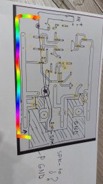
- Your amp will work, I see nothing weird in it.
- Suppose BD139, etc, are there only to feed simulator, lacking accurate MJ11*** Darlington models?
- Darlingtons are not intrinsically weaker than comparable discretes.
Statistically (we are talking thousands of amps here) they have been very robust.
Not sure about yours, but why would they be weaker?
- No way you can get 150W into 4 ohm using meager 35V rails
- No way 20A or anything near that will happen there, worst case is 30V (considering transistor and ballast resistor drop) into 3.2-3.5 ohm DCR so less than 10A peak.
Yes, better voltage specs also yet nominally same SOA (or very close).
Officially 10A instead of 15A but in practice that has not changed anything.
Officially 10A instead of 15A but in practice that has not changed anything.
Nobody in the entire thread suggested using a 2n3055 at 10A. In post #2 I suggested 2 pairs of mj15015/16 to achieve 150 W, or 3.05 amps each. Back when my vision was substituting MJ15015 for MJ11015. Aged brains substitute the familiar images for the new; you have seen it all before.That’s right. In practice it doesnt change anything because at 10 amps or above the current gain in the 3055 is useless.
XXbrunoxx original schematic had 2sa1943 2sc5200 as output transistors in his sim model. Which have less soa than MJ15015/16.
Last edited:
No, but you could probably get away with using TIP142/7, which in practice, are better than 3055/15015. If TIP142’s wont explode certainly 11015’s would be plenty safe. No epoxy case to send pieces flying around the room if you hook ‘em up backwards, either.
I did 😉Nobody in the entire thread suggested using a 2n3055 at 10A.
I made some 8000 100W Bass amplifiers between 1969 and 2004-2008 when I switched to TIP142/147 because I could not get 2N3055H any more and Epitaxial ones couldn't handle the stress no matter who makes them.
Last 1000 or so used incredibly robust UR/USHA India made ones.
+/-42V rails into 4 ohm loads lead you straight to 10A land.
On +/-35 volts it won’t happen. And 100 watts at 4 ohms is probably even in question, unless you used a 600 VA transformer to get the regulation in the 92% range. 80% is more what you typically see and that puts you at 80 watts.
OP might consider upping that voltage to make power. +/-40 or even 42 is still safe with MJ11015/6. Or even the TIP142/7 but there is far less margin there. Can’t crank either much higher due to encroaching on the second-breakdown limits. +/-50 volts with the bigger pair results in blown devices. Ask me how I know. MJ15003/4 and a driver holds up fine.
MJ11015/6 are likely prohibitively expensive in Argentina. Getting crazy enough here - if you can even still get them. I still have a handful, and some of the 014’s. When they’re gone they’re gone - won’t order more at todays prices and the surplus house I got mine from folded after Covid (owner has been thinking about retirement anyway). They we’re real - it was just across town and I could buy and try - and go get a bunch if they worked out. The TIPs are something I keep a small stock of. Not something I use in any major builds but if/when I run out another 10 each would be on the next Mouser order.
O.P. wants 150 watts. Has not stated speaker impedance. Why I suggested 2 pairs MJL3281/1302 with TO220 drivers like MJE15028/29. Current into 4 ohm resistor 3.05 amps each. 35 v 1 sec soa about 2.5 amps. AndrewT said something about DC soa rule for O.T. survival allowing some margin for increase of current with inductors over the resistive calculation. MJ21195/196 1 sec soa about 5 amps at 35 v 4 amps at 50 v.. In US all TO3 ON transistors nearly same price. >$10.On +/-35 volts it won’t happen. And 100 watts at 4 ohms is probably even in question, unless you used a 600 VA transformer to get the regulation in the 92% range. 80% is more what you typically see and that puts you at 80 watts.
Last edited:
- Home
- Amplifiers
- Solid State
- Simple Sub amp