Motor run capacitors are designed to have very low ESR, and when used as the last cap in the power supply can lower the power supply impedance. Its your job to decide where their advantages outweigh the cost and size penalties. Isn't DIY grand? 😉
Hi,
How can we identify motor run versus motor start capacitors. My surplus store is not very descriptive on what is in the box. Is there a way to tell which is which?
Thanks
How can we identify motor run versus motor start capacitors.
It is not always possible without seeing the original manufacturers description. If you can get the manufacturers part number, maybe Google can help. I can offer one hint. Avoid any cap in a plastic can. All of the good ones that I have seen are aluminum. Many motor start caps come in a black plastic housing.
Hi,
I want to know more about transformer orientation. How can I avoid problems with transfo-transo and transfo tube interference? My layout is not completely done, so I try to avoid problem, not to patch some, yet
Thanks,
I want to know more about transformer orientation. How can I avoid problems with transfo-transo and transfo tube interference? My layout is not completely done, so I try to avoid problem, not to patch some, yet
Thanks,
Hi,
What is the best output transformer orientation (A, B, C or D)?
What is the best power transformer orientation (i, ii, iii, iv)?
Do not worry to talk about combination (e.g. A and ii).
A: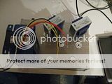
B:
C: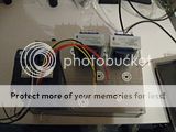
D: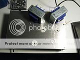
i: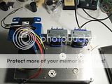
ii:
iii:
iv:
P.S. Do not worry, I will put the power transformer upside down when I will fix it 😉
What is the best output transformer orientation (A, B, C or D)?
What is the best power transformer orientation (i, ii, iii, iv)?
Do not worry to talk about combination (e.g. A and ii).
A:

B:

C:

D:

i:

ii:

iii:

iv:

P.S. Do not worry, I will put the power transformer upside down when I will fix it 😉
I have never seen OPT's interfere with each other. I have seen the power transformer and the OPT's fail to get along with each other. You want thier cores at 90 degree angles from each other. So I would choose option i or iv. Use iv if you ever want to sdd a choke later, and put it behind the power transformer
Rk
Hi,
How critical is the Rk value:
-match between left and right
-match with the expected value of 560ohm.
The reason I ask is that my 560ohm 5w measure a bit lower and the match left-right is not perfect. Is this critical?
I will use el34 with a edcor XPW035 ( 120Vrms, 60Hz. 740V(370-0-370)@200mA, 6.3V(3.15-0-3.15)@5A & 5V@2A)
The answer is probably here, but I don't know how to interpret the table.
Value of C1, C2, C12 & C22 critical?
hi,
pardon for hijacking this thread.
Recommended C1 = 47uf/500V, C2 = 120uf/500V & C12 = C22 = 1500uf/50V.
Am i also able to use C1 = 100uf/500V, C2 = 220uf/500V & C12 = C22 = 2200uF/63V?
Thanks.
hi,
pardon for hijacking this thread.
Recommended C1 = 47uf/500V, C2 = 120uf/500V & C12 = C22 = 1500uf/50V.
Am i also able to use C1 = 100uf/500V, C2 = 220uf/500V & C12 = C22 = 2200uF/63V?
Thanks.
Those are fine except for C1. If you are using a tube rectifier especially, you really shouldn't exceed 47uF.
Those are fine except for C1. If you are using a tube rectifier especially, you really shouldn't exceed 47uF
How about 56uf 500v?? Digikey is out of the 47uf 500v. Just wondering
Those are fine except for C1. If you are using a tube rectifier especially, you really shouldn't exceed 47uF.
hi russ,
thanks for the reply.
am still learn and a lot more to learn since i am not electrically inclined. got to be careful cos do not wish to get myself hurt. what is the reason behind not exceeding 47uf? is it due to the filtering of power noise? (read some article from zero distortion about power supplies meant for chipamp/SS - lower uf is able to filter higher freq noise much faster than higher uf cap). i am assuming C1 & C2 are power supply reservoir cap & am i rite?
hi gasser-dude,
as russ replied, C1 should not exceed 47uf.
It has to do with the peak forward current that must be passed by the rectifier to charge the cap. Since the diode only charges the cap for about 1/4 of the cycle and the cathode can only conduct so much current at a time, this limits the size of that first cap. The data sheets for rectifiers often note this explicitly or via a table. The second cap is sufficiently isolated from the diode that is doesn't matter.
If you have no idea what I am talking about, look here:
http://www.freewebs.com/valvewizard/fullwave.html
If you have no idea what I am talking about, look here:
http://www.freewebs.com/valvewizard/fullwave.html
what is the reason behind not exceeding 47uf?
Here is my real (overly) simple explanation:
The rectifier tube supplies the power for the entire amplifier. In the Simple SE this means that one tube must pass enough current to feed four tubes, so it has a tough job.
The filter capacitors store a reserve supply of energy to feed these four hungry tubes during times when they want more than the rectifier tube can deliver. They are completely empty when the amp is switched on. The amplifier tubes don't get to eat until the resovoir is full.
Now, upon flipping the power switch the four amplifier tubes get their wake up call, and can sit at the table awaiting the rectifier tube to feed them their breakfast.
The rectifier tube is slapped out of bed, told to immediately begin filling the resovoir before it is awake yet (cathode warmed up) so that the amplifier tubes can have their breakfast. If the resovior (first cap) is too big, the rectifier tube will have a heart attack before it can fill it!
OK, overly simple somewhat stupid explanation, but that is what happens. The rectifier tubes made today seem to be of a lesser quality than those made in the past. If the coating on the cathode is not of a uniform thickness, and the plate to cathode spacing is not constant, the problem is worse.
The rectifier tube must begin to pass current as it is warming up. If the spacing inside the tube is not uniform the current will flow in one localized area, leading to fireworks inside the tube. For this reason the first cap (C1) should be kept as small as possible. If a choke will be used, a 33, or 39 uF cap might be a better choice than a 47 uF.
Hi everyone, I was thinking about build a second Simple SE. I was wondering if I need C12 and C22 if I am not using CFB. I was going to build it point to point. Or does that grid need to be connected to something?
I am going by the schematic on the website.
I am new at this.🙂
I am going by the schematic on the website.
I am new at this.🙂
Output Impedance
Hello George and All,
This thread looks like the place to ask Simple SE questions. I am the proud user of two Simple SE’s. Just for grins I have been rolling tubes and transformers with speakers and headphones with and without feedback. The question came to mind regarding output impedance and the impact on bass response. George I recall you recommending against testing against with no load connected. There was also mentioned a spreadsheet that would calculate the Zo using two different connected load values. Is it possible to post the procedure and spreadsheet?
Thank You
DT
All just for fun!
When you say no load connected, I assume you're referring to having nothing connected to the OPTs with the amp on? If so, very very bad idea. Pretty quick way to kill tubes and components in that area of the amp IIRC.
Hello,
I searched online for a output impedance test procedure. The procedure that I recall involved testing one condition with say a 8 ohm load attached and another with only the Volt meter attached. Yes with the amplifier on. Yes I know that this is bad pie.
I have given this some thought. The finger experiment goes this way.
My target amplifier has a 5000 ohm to 300 ohm output transformer. If my thought process is correct the load and the amplifier internal resistances are in series. If I connected load is 300 ohms the resistance will be 300 + Zo. Now put a sine at the input and adjust the input voltage to end up with a nice round 10 volts at the output. Now adjust the connected load so that the output voltage is half (5) of the original 10 volts. The total series resistance will now be double the original. Now measure the connected load resistance divide by 2 subtract 300 and that is the output impedance.
What do you think? Did I go south?
DT
All just for frun!
Hi I was just wondering if anyone has ever put in a Treble control on their Simple SE? If so does anyone have a schematic?
Hi! Long time lurker, first time poster here. After being stuck at home with covid a few weeks back I decided I would finally build myself a tube amp. I’m extremely fascinated but very intimidated by diy audio as my understanding of electrical engineering stops at wiring old motorcycles. Anyway, here’s what I’m thinking:
PT- Hammond 274BX
OPT - Edcor Xse15-8-5k
choke - Hammond 193h
coupling caps - Auricap 3.6uf at 450V
tubes:
kt-88
mullard 12AT7
gz-34 (rectifier)
Im planning to use this amp to power a pair of Klipsch speakers- 8ohms, sensitivity: 90db spl @ 1W/1 meter. I listen to vinyl almost exclusively.
Does this set up look ok? I’ve been obsessively reading both here and on the tubelab site, as well as in the literature recommended in the tube forum stickys.
I have a few more questions about sourcing parts and other noob stuff but maybe I can look into that after I get this part sorted. 🤷♂️
Any help would be very much appreciated. Thanks!
- Home
- More Vendors...
- Tubelab
- Simple Simple SE questions