I can take all of the parts off of a board using a propane torch and use them to build a new board. It takes me about an hour total.
A heat gun also works for this quickie depop, but like the torch it is very stinky. About the best way to liberate soldered PCB sockets. Should say I guess that the board does NOT survive (it makes the stink) 😀
Hi,
What is the recommended fuse value (amp and voltage) and type (fast or slow)? My main is 120V.
Thanks
What is the recommended fuse value (amp and voltage) and type (fast or slow)? My main is 120V.
Thanks
Hi,
What is the recommended fuse value (amp and voltage) and type (fast or slow)? My main is 120V.
Fast blow, 1.5 amp should be fine. If it gives you problems, try a 2 amp instead.
Hi,
What is the official name of the gommets
http://www.tubelab.com/images/AssemblyManualSimpleSE/AmpIndustrialStrength/ChassisPunched3_b.jpg
and where can we find them (electronic, hardware, plumbing, or else type of store)?
Thanks,
What is the official name of the gommets
http://www.tubelab.com/images/AssemblyManualSimpleSE/AmpIndustrialStrength/ChassisPunched3_b.jpg
and where can we find them (electronic, hardware, plumbing, or else type of store)?
Thanks,
Hi,
What is the official name of the gommets
http://www.tubelab.com/images/AssemblyManualSimpleSE/AmpIndustrialStrength/ChassisPunched3_b.jpg
and where can we find them (electronic, hardware, plumbing, or else type of store)?
Thanks,
Radio shack has a grab bag of them that is what I used on my first Simple SE. It will set you back about $2. On my second I am trying to find some that will work with 1/8" thick aluminum. The radio shack ones dont work all that well with it.
I am trying to find some that will work with 1/8" thick aluminum.
Try looking through the selection at Mouser. I managed to squeeze one of these onto my chassis plate. It is snug, but it works. They probably have something even better.
744 Keystone Electronics Mounting Hardware
Hi,
1. Can we use this trick for the volume control?
ESP - A Better Volume Control (A 100k linear with a 15k "in parallel")
2. Do we have to isolate the css from the heatsink (not thermally, but electrically)?
1. Can we use this trick for the volume control?
ESP - A Better Volume Control (A 100k linear with a 15k "in parallel")
2. Do we have to isolate the css from the heatsink (not thermally, but electrically)?
1. Can we use this trick for the volume control?
ESP - A Better Volume Control (A 100k linear with a 15k "in parallel")
I'd just blow the $10 on an Alps RK27-series pot at Mouser. I'm using one in one of my designs and have not noticed any discontinuity in the logarithmic action. That doesn't necessarily mean there isn't a discontinuity - just that I haven't noticed...
2. Do we have to isolate the css from the heatsink (not thermally, but electrically)?
The CSS has B+ on it. If the heatsink is electrically connected to anything else or is mounted in a position where someone could touch it, I would definitely isolate the CSS and prevent access by children's fingers, etc. to the tab of the CSS's TO-220 package. If the heat sink is internal in the chassis, then all you need is some thermal grease.
~Tom
I'd just blow the $10 on an Alps RK27-series pot at Mouser. I'm using one in one of my designs and have not noticed any discontinuity in the logarithmic action. That doesn't necessarily mean there isn't a discontinuity - just that I haven't noticed
Hi,
I am more concerned about the impedance of the pot. Would it be ok? ESP - A Better Volume Control
Thanks
I am more concerned about the impedance of the pot. Would it be ok?
The input impedance (seen by the source) of the Simple SE with a simple pot for a volume control will vary slightly as the control is turned. It is roughly equal to the value of the pot (50 to 100K) when the pot is all the way down and gently drops to the value of the pot in parallel with the 220K resistor that is on the PC board (R11 and R21) at full volume (about 70 K with a 100K pot). If R11 and R21 are replaced with 15K resistors the input impedance of the amp will vary from 100K to 14K as the volume control is turned up. If your source is OK with that then this trick will work. The Simple SE doesn't care. Most solid state sources (like a CD player) will be OK, but a vacuum tube preamp or line stage may not like it.
On my second I am trying to find some that will work with 1/8" thick aluminum. The radio shack ones dont work all that well with it.
Try McMaster-Carr They have zillions of grommets. They also have rubber vibration mounts etc if you want to get even more exotic.
My hardware store locally actually had a great selection of larger sizes.Try McMaster-Carr They have zillions of grommets. They also have rubber vibration mounts etc if you want to get even more exotic.
Hi,
Some more questions:
1. What are the characteristics of the ICL (min 2A), but R@25 and R@current?
2. Is there a problem to put R17 and R27 under the board with mini binding post ( http://media.digikey.com/pdf/Data Sheets/Keystone Electronics PDFs/8737.pdf )?
3. How do you fix the ICL? I want to avoid exposed current and this ICL is a bugger. Do you fix it at the switch, at the power input, other?
4. Can you tell me more about the transformer orientation. What should I avoid (transfo-transfo and transfo-tube)? My plan is to have the power and the output transformer at the top and the choke under.
Thanks,
Hi,
Some more questions:
1. What are the characteristics of the ICL (min 2A), but R@25 and R@current?
Thanks,
Typically a CL-090 is used, with 120 ohms at 25 deg C and about 1 ohm at rated current. This limits current to about 1 amp when the ICL is cold.
This goes in series with your hot mains wire, at the switch, power input, or on the transformer primaries, anywhere between the power cord and the primarys of the power transformer.
here is the digi-key P/N: Digi-Key - KC009L-ND (Manufacturer - CL-90)
Typically a CL-090 is used, with 120 ohms at 25 deg C and about 1 ohm at rated current. This limits current to about 1 amp when the ICL is cold.
here is the digi-key P/N: Digi-Key - KC009L-ND (Manufacturer - CL-90)
Thanks,
There are currently out of stock, so I was looking for alternatives.
Hi,
Some more questions:
1. What are the characteristics of the ICL (min 2A), but R@25 and R@current?
2. Is there a problem to put R17 and R27 under the board with mini binding post ( http://media.digikey.com/pdf/Data Sheets/Keystone Electronics PDFs/8737.pdf )?
3. How do you fix the ICL? I want to avoid exposed current and this ICL is a bugger. Do you fix it at the switch, at the power input, other?
4. Can you tell me more about the transformer orientation. What should I avoid (transfo-transfo and transfo-tube)? My plan is to have the power and the output transformer at the top and the choke under.
Thanks,
Hi,
I have some more questions.
I received my tubes and sockets. I try to fit them in, but it is quite hard. Fortunately the sockets are not yet on the board, because of the force required to push the tube all the way down the socket would have probably break th board! Is this normal? How do you "train" your tube/socket so they can be replace while on the board?
If I want to keep my options open (ul switch and cathode follower switch) what wire should I avoid to mix? There will be two dpdt switch going in and out of the output transfo.
thanks
I received my tubes and sockets. I try to fit them in, but it is quite hard. Fortunately the sockets are not yet on the board, because of the force required to push the tube all the way down the socket would have probably break th board! Is this normal? How do you "train" your tube/socket so they can be replace while on the board?
As long as the PCB is on a flat surface, there is no danger of breaking it. Breaking-in new sockets an be a little scary, especially the noval ones. I have a couple of crusty old tubes that I use to get new sockets through their first time.
If I want to keep my options open (ul switch and cathode follower switch) what wire should I avoid to mix? There will be two dpdt switch going in and out of the output transfo.
I'm afraid I don't follow. Are you asking which wires not to mix-up? The answer is all of them. 🙂
Hi,I'm afraid I don't follow. Are you asking which wires not to mix-up? The answer is all of them. 🙂
What worries me is that my pcb will be suspended. Plus, the 9-pin won't be flat on the pcb, it will slightly rise to match the height of the 8 pins (like in the manual).
Which wires should be twisted, which one should be in parallel, which one should be perpendicular? I am trying to design a spaghetti bowl without harmful interference.
Thanks
What worries me is that my pcb will be suspended. Plus, the 9-pin won't be flat on the pcb, it will slightly rise to match the height of the 8 pins (like in the manual).
Unless you have a particularly flimsy socket, you will be fine. Did you use the AES part listed by George?
Which wires should be twisted, which one should be in parallel, which one should be perpendicular? I am trying to design a spaghetti bowl without harmful interference.
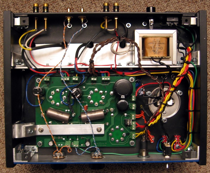
All AC-carrying pairs should be twisted together and pushed into the corners of the chassis where possible. This means the primary and each pair of secondaries coming out of the power transformer. You can further reduce cross talk by avoiding running power supply wires in parallel with signal carrying ones (input, CFB, UL switch wires, for example). Other than that, it doesn't matter too much. The most sensitive wires will be from the input jacks to the PCB. Keep these away from everything else as much as possible.
For example, all of the switch wires on my SSE are bundled in parallel. They don't seem to cause any issues.
Unless you have a particularly flimsy socket, you will be fine. Did you use the AES part listed by George?
I got the generic ceramic sockets from partsconnexion.
- Home
- More Vendors...
- Tubelab
- Simple Simple SE questions