Your dummy load resistor seems to be a 3W type, and it will be on flame with 20W across it. Your subjective loudness comparation with the class-D amplifier is revealing. Class D amplifier clipping sound nasty, so you notice even the smallest bit of it. Clipping on most tube amplifiers (and especially the one you have built) is less noticeable so you can turn the volume level up more; how much also depends from the type of music you are listening and from the speakers.
As side note, I have a China-sourced multimeter identical to the one I see in your picture across the high voltage power supply, but I use it only for low voltages because the class type stamped on the panel and on the probes is bogus (just open it and check for yourself). Do not even attempt to measure anything near the 1000V listed on the range selector, it will be dangerous. I suggest to use better probes and meters if you want to work on tube amplifiers. I would be not at ease using that instrument on a typical 250-300V small tube amp.
As side note, I have a China-sourced multimeter identical to the one I see in your picture across the high voltage power supply, but I use it only for low voltages because the class type stamped on the panel and on the probes is bogus (just open it and check for yourself). Do not even attempt to measure anything near the 1000V listed on the range selector, it will be dangerous. I suggest to use better probes and meters if you want to work on tube amplifiers. I would be not at ease using that instrument on a typical 250-300V small tube amp.
You are right. The 91Hz sine was created using my phone at it's highest volume (~2V P-P). With music coming out of it and using this amp with the phone volume at it's highest, the distortion created is clearly noticeable. I usually lower it by 2 steps and then the distortion becomes unnoticeable. I think the last 2 steps are software amplification.
I have tried folk, rock, hip-hop and even MIDI on it and it still sounds fine.
About the multimeter, don't worry. I know these are awful, but I can't afford anything good like a Fluke or something. I have owned a few cheap but definitely better than this multimeters and I've fried them all because of high voltage. Note that this has been half-dead; the amps range and transistor gain tester part have been fried. I have made that Arduino based multimeter which has a 16 bit ADC with 0.25% resistors which have been calibrated. I use that for voltages less than 50V.
As you might have noticed, I'm a bit of a noob when it comes to tubes. I have bought 2 PCL805s and a PY88 as my first tubes and have started experimenting. Most of the class A amps with this tube on the internet don't work LOL.
OK now this is frustrating. My oscilloscope is stuck on a boot loop :/
The screen is all white and flashes the trigger LED just like when it's trying to boot but it resets and keeps flashing indefinitely.
The screen is all white and flashes the trigger LED just like when it's trying to boot but it resets and keeps flashing indefinitely.
I probably won't be able to change the transformer. Too bad my oscilloscope got fried and I won't be able to measure the output power 🙁
Thanks for the reply!
Thanks for the reply!
Yeah. I just this cheapy does it accurately at 91Hz.
One more question
This class A amplifier I've built has this weird feedback-like thing when it doesn't have input audio or is not connect to a device. I have added a "mute" switch which shorts out the gate of the pentode to eliminate the ear piercing noise. How can I remove this feeback thingy?
One more question
This class A amplifier I've built has this weird feedback-like thing when it doesn't have input audio or is not connect to a device. I have added a "mute" switch which shorts out the gate of the pentode to eliminate the ear piercing noise. How can I remove this feeback thingy?
Yeah. I just this cheapy does it accurately at 91Hz.
I just hope*
This class A amplifier I've built has this weird feedback-like thing when it doesn't have input audio or is not connect to a device. I have added a "mute" switch which shorts out the gate of the pentode to eliminate the ear piercing noise. How can I remove this feeback thingy?
Please show the schematic.
I'll draw it and post, but I don't know how to attach images. I don't see the paper clip icon, I just see the attach image with a link icon.
Below the Message board is Go Advanced-button. Press it.
Then will appear an other button: Manage Attachments.
After pressing that, you may select and upload the file you wish, such as a schematic.
Then will appear an other button: Manage Attachments.
After pressing that, you may select and upload the file you wish, such as a schematic.

Hey guys
I'm looking for a simple-ish PCL805 push-pull amplifier which has been proven to work.
I have 2 PCL805s, a 170V power supply, and a transformer.
I have made a class A amplifier using one of those tubes and it sounds great with about 20W of power at a 3Ohms speaker ( 2 x 6Ohms ).
I would like it to have only 2 PCL805s and no solid state devices except diodes.
Thanks, guys!
I think you can not get 20W with PCL85, but 12W (max) can be obtained very lightly, and at 10W THD <1%. So the diagram is the one below, the voltage amplifier and the defazor (Cathodina) are inspired by the colleague @ Davorin, a very inspired scheme. Maybe this configuration will help you.
Attachments
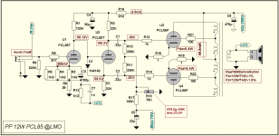
I think you can not get 20W with PCL85, but 12W (max) can be obtained very lightly, and at 10W THD <1%. So the diagram is the one below, the voltage amplifier and the defazor (Cathodina) are inspired by the colleague @ Davorin, a very inspired scheme. Maybe this configuration will help you.
Hello
As the other fellow members showed me, my calculations were wrong.
Thank you for the schematic!
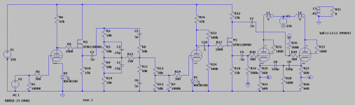
I've built several amps with the ECL/PCL805/6GV8/6F5P. Here's one:
https://www.diyaudio.com/forums/ins...undred-buck-amp-challenge-43.html#post5962424
Just ignore everything to the left of R7 and substitute the second triode for the MOSFET. It uses a garter bias and triode strapping on the output pentodes. The garter bias can be eliminated by getting rid of (shorting over) R21, R26, and R28. Also C10 is probably not necessary unless your source is very weak.
Attachments
This site has some useful design guides for this family of tubes:
SPICE Design of 6F5P SET Amplifier
SPICE Design of 6F5P SET Amplifier
I've built several amps with the ECL/PCL805/....
Passive baxandall tone stack is wrongly and poorly designed. Upper caps must be smaller than those in the top sites and vice-versa with resistor values, for proper operation of it.
- Home
- Amplifiers
- Tubes / Valves
- Simple PCL805 push-pull amplifier