Hi X - excuse my limited knowledge on the TL subject - what is the total length of the line in the build? assuming this is 1/4 tuning wavelength? also, would one be able to put their own tweeter in place of the RS waveguide setup you have?
Now my PR project is complete I'm looking at my next challenge.
Now my PR project is complete I'm looking at my next challenge.
Hi Mainframe,
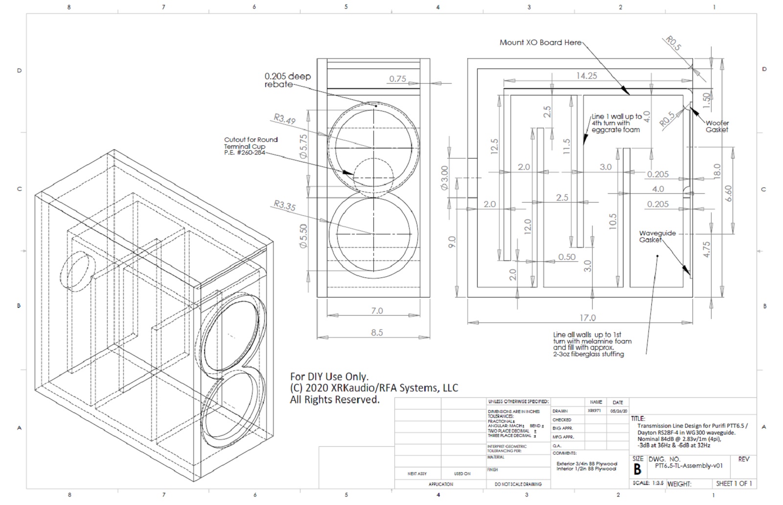
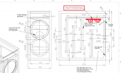
A good back of the envelope guess is to take the lengths of the segments and add them up. So there are 5x 14.5in long segments. Plus the last one is about 16in.
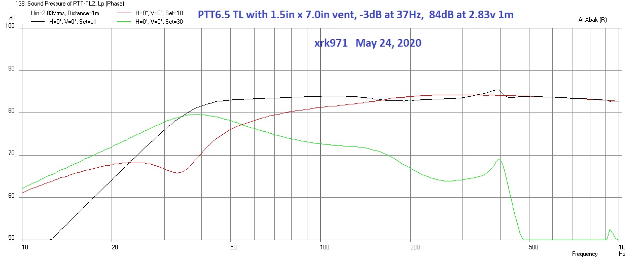
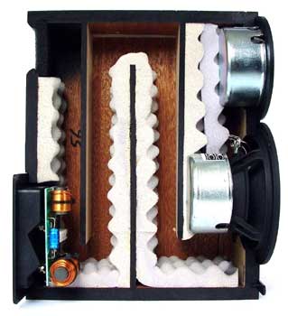
5x 14.5 + 16 = 88.5in or 2.25m. This has 1/4-wave frequency of 38Hz. In reality it’s a little lower since it’s tapered. And looking at the predicted response, we see the dip in the driver response at about 34Hz (red curve dip corresponds to TL tune frequency). Depending on stuffing, you can tune it down to 32Hz and up to 43Hz.
Dip in front driver output at 34Hz:
You can indeed put your own favorite tweeter here. Which is why I am making a removable front baffle - to allow changing the tweeter. You can also flip it around for tweeter on top in traditional sense. Putting speaker wire terminal cup in middle of the back allows this flip to be seamless.
A good back of the envelope guess is to take the lengths of the segments and add them up. So there are 5x 14.5in long segments. Plus the last one is about 16in.
5x 14.5 + 16 = 88.5in or 2.25m. This has 1/4-wave frequency of 38Hz. In reality it’s a little lower since it’s tapered. And looking at the predicted response, we see the dip in the driver response at about 34Hz (red curve dip corresponds to TL tune frequency). Depending on stuffing, you can tune it down to 32Hz and up to 43Hz.
Dip in front driver output at 34Hz:
You can indeed put your own favorite tweeter here. Which is why I am making a removable front baffle - to allow changing the tweeter. You can also flip it around for tweeter on top in traditional sense. Putting speaker wire terminal cup in middle of the back allows this flip to be seamless.
Last edited:
If the line is approx 89” as I calculated it then this would give a quarter wave tuning of 30hz (MH-Audio calculator) which matches my Leonard and XRK’s models reasonably well.
Whilst I am on, @mainframe99, I saw you did a minidsp crossover for the purify 6.5 (is this the 4 ohm version) with a 26adc using the Harsch scheme that looked very good, any chance you would be willing to share the settings via PM if I send you a message (personal use only).
(Sorry emails crossed in the ether).

The compliments go to my cabinet maker. He’s very good and I am lucky he is local and enjoys audio too.
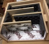
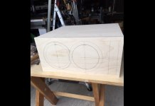
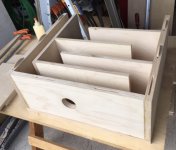
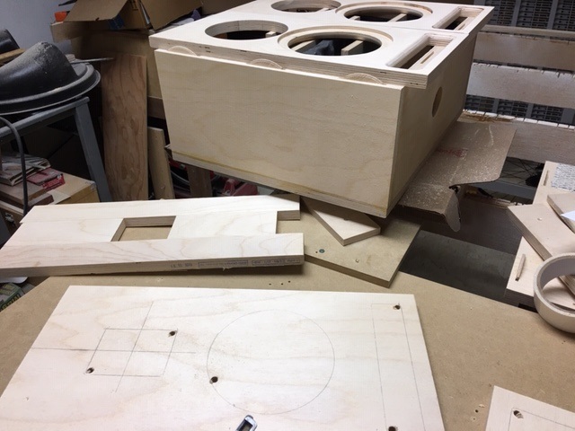
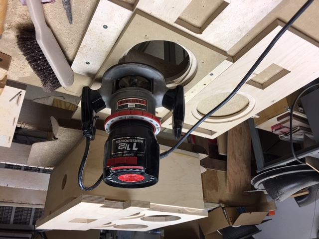
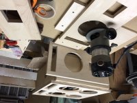
Looking good!Installing butyl damping sheets and eggcrate foam. More foam will be added over on top of the buytl/foil sheets.
Is it critical the thickness of the eggcrate foam?
The eggcrate is used to reduce the transmission of mids and highs to the port/vent. There are many turns, so a thinner one is ok. With a plain box and vent, thicker 2in foam might be better. I probably could use thicker 2in in main rear chamber but we will see how this one goes. I can always add more or swap out as front baffle is removable.

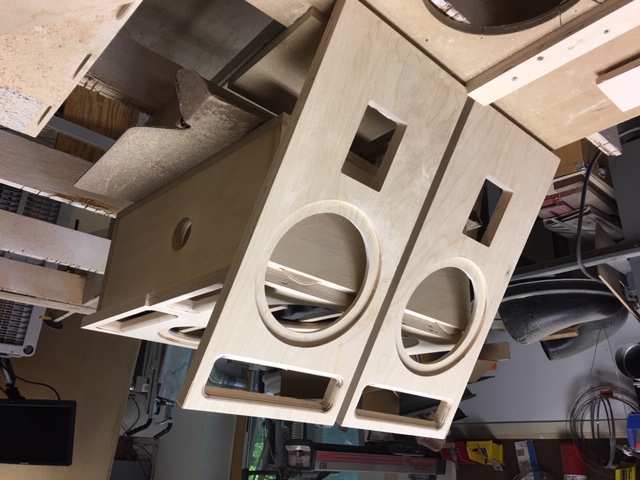
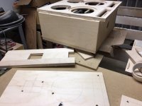
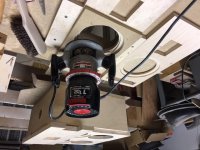
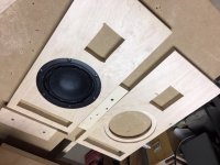
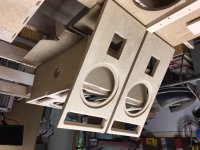
Some process/progress photos from my cabinet maker - he is doing an awesome job!


I am hoping to get them by mid next week I think. If I am lucky, maybe as early as this Friday.
I am hoping to get them by mid next week I think. If I am lucky, maybe as early as this Friday.
Attachments
Be careful, you're not supposed to put any damping on the walls. 😉The eggcrate is used to reduce the transmission of mids and highs to the port/vent. There are many turns, so a thinner one is ok. With a plain box and vent, thicker 2in foam might be better. I probably could use thicker 2in in main rear chamber but we will see how this one goes. I can always add more or swap out as front baffle is removable.
Using sound absorption to reduce standing waves
I put a wad of fiberglass or polyfill in the main section behind the drivers to the first turn. The damping on the walls is used extensively by PMC - who developed the TL shape I am using. If extra damping is needed, a small wad can be placed in the rear section near the terminal cup. But I haven’t found this to be necessary. The best way is to tune it while measuring the impedance sweep. That tells all.
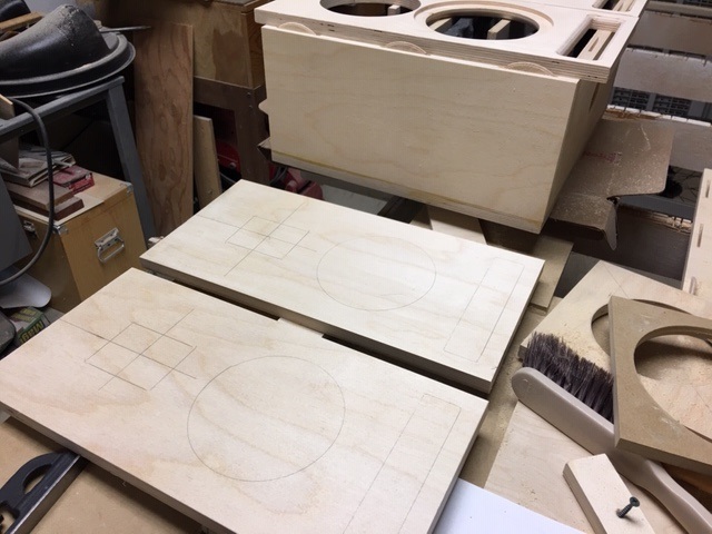
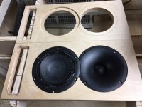
More progress and getting closer and closer to finished. The spare set of baffles for the RAAL tweeter are now completed.
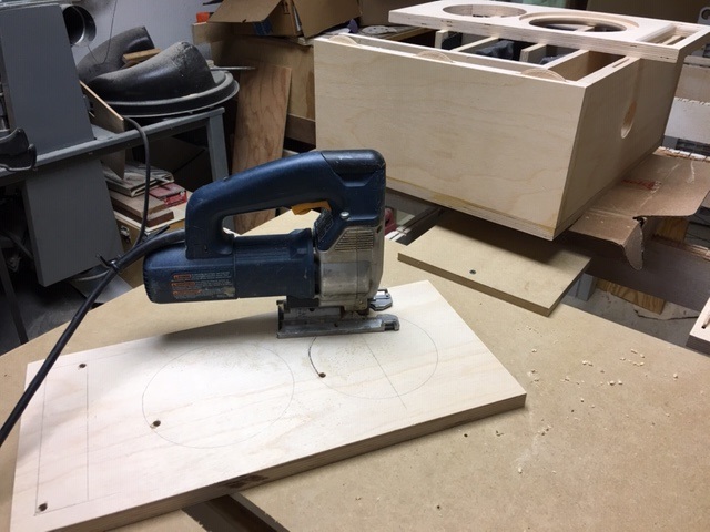
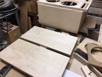
Laying out cuts for the spare baffle RAAL 70-20xr tweeter:
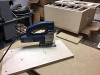
Cutting the rebates for the PTT6.5 on the spare baffle for the RAAL tweeter:

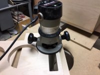
Using template/jig to cut the rebates for the woofer:
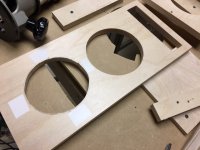
Checking for a nice tight fit with the PTT6.5:
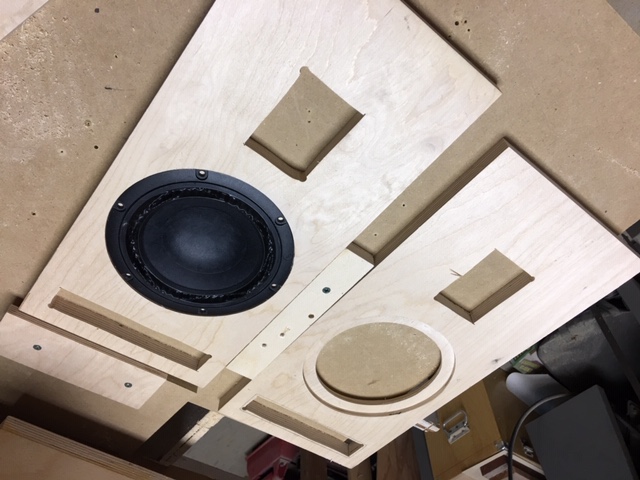
New spare set of baffles for the RAAL twetter completed:
Fit check with the WG300 and the PTT6.5 looks great:

Laying out cuts for the spare baffle RAAL 70-20xr tweeter:
Cutting the rebates for the PTT6.5 on the spare baffle for the RAAL tweeter:
Using template/jig to cut the rebates for the woofer:
Checking for a nice tight fit with the PTT6.5:
New spare set of baffles for the RAAL twetter completed:
Fit check with the WG300 and the PTT6.5 looks great:
Attachments
-
 PTT6.5-TL-build-progress-07.jpg94.5 KB · Views: 2,342
 -
 PTT6.5-TL-build-progress-08.JPG116.8 KB · Views: 1,009
 -
 PTT6.5-TL-build-progress-09.JPG128.8 KB · Views: 1,955
 -
 PTT6.5-TL-build-progress-10.JPG111.6 KB · Views: 989
 -
 PTT6.5-TL-build-progress-11.JPG119.7 KB · Views: 1,960
 -
 PTT6.5TL-build-progress-13.JPG101.6 KB · Views: 1,987
Last edited:
- Home
- Loudspeakers
- Multi-Way
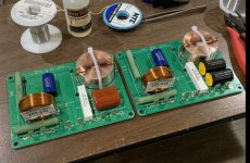
- Simple Passive Harsch XO Using PTT6.5 and RS28F in a Waveguide