Mr. Johnson,
Finally am taking your advice.
Ordered the clapper from Dmitri and an oscilloscope, my first. Big step for me.
I am thinking with the capacitors being able to be inserted so easily it would be easy to use the components on the board you intend to use in the circuit.
This is so obvious I do not doubt it has been said before. I have read through the thread so I could have missed it.
Thanks for providing the initiative, good advice and a neat tool.
Congratulations, rickmcinnis! Please post a couple scope photo of your 'Modo in action once everything is working to your satisfaction: "before" (much ringing, zeta << 1), and "after" (critical damping, zeta=1.0). Receive accolades.
Got my kit from dsolodov yesterday and it is WELL DONE!
Super high quality PCB that will last forever and parts well marked.
dsolodov has made it easy to put this to work. His price is more than fair and his response to my order was immediate.
Another fine audio fellow. We are lucky to have such folk in our hobby
Thanks, dsolodov. (and of course Mark Johnson)
I think he simply emailed my original PCB layout Gerber files (attached to post #1 of this thread) to a PCB fab and ordered a batch of boards. Which is what I thought might happen when I put the design in the public domain. Good on ya, both.
You can see my inexperience as a PCB designer in Sept 2013, by noticing that I left the topside silkscreen text for the mounting holes intact (!). You can see it on the Gerbers and several PCB fabs let it appear on the finished boards. I wish I had told KiCad to prevent that text from appearing.... but I didn't RTFM to learn it was even possible, until many months after QM V.4 taped out.
You can see my inexperience as a PCB designer in Sept 2013, by noticing that I left the topside silkscreen text for the mounting holes intact (!). You can see it on the Gerbers and several PCB fabs let it appear on the finished boards. I wish I had told KiCad to prevent that text from appearing.... but I didn't RTFM to learn it was even possible, until many months after QM V.4 taped out.
I remember you mentioning that but that's easy to deal with.
dsodolov had the boards made with the same material thickness John Broskie uses. I think this is a nice touch especially since I cannot imagine us ever changing out components. Really solid & rugged.
Can't wait to figure out how to use the 'scope and get the myriad transformers in my system critically damped.
Mr. Johnson,
Haven't got my parts yet to start using QUASIMODO. Caps on the way, next week will be my introduction to 'scope use.
In the interim I took a look at the RING NOT supply and see the values used for this are very different from what you recommend we use with QUASIMODO.
Just curious why these are so different and should we experiment with different values of capacitance?
Is there a simple explanation for why you chose those values?
Thanks,
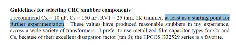
I think you might be talking about this paragraph in the Quasimodo design note (p. 7), click to see it full size:

The paragraph is aimed principally at readers who've never snubbed a transformer secondary circuit before, and who've never used a bellringer test jig before, and who've never solved a second order differential equation in their life. It suggests a starting point for Quasimodo experimentation.
People who have snubbed a transformer, who have used bellringer jigs before, and who have solved lots of second order differential equations, include myself and many other EEs. They don't need quite so much hand-holding and I am not afraid to give then plenty of rope, knowing they won't hang themselves.
My bottom line recommendation is: If you know what you're doing, you don't need my advice: have a jolly time designing however you wish. On the other hand: if you don't know what you're doing, follow the suggestions in the design note. They're optimized for safety, and are maximally forgiving of rookie mistakes. One common rookie mistake is analysis paralysis; try to avoid that one too.
_
Attachments
Last edited:
I am certainly going to start with the suggested values. those are the ones I ordered.
Just curious as to what are the benefits of going beyond the basic recommendation as you did with the RING NOT supply snubber.
It certainly would be easy to enough to just put in random values for the C's and see what happens which I will likely do just to get a feel for it.
Was curious if you would tell us why those values are so different. You had mentioned about using up to 3uF for C2 and for RING NOT you have doubled the value from the suggested but this seems to have allowed (my uneducated guess) a lower value for C1. Is this typical that a higher value for C2 allows a lower value of C1?
Trying to get your rectifier article but waiting forever to receive my account verification. I guess Dutch computers take Sundays off?
Nope, I'm not going to explain the differences between an expert's approach and the approach recommended for beginners. It might encourage beginners to imagine they are experts, and naively do something very unsafe.
Here's a poem by Stephen Crane that touches upon the topic of obligation. Google can tell you more about it.
A man said to the universe,
“Sir, I exist!”
“However,” replied the universe,
“The fact has not created in me
A sense of obligation.”
Here's a poem by Stephen Crane that touches upon the topic of obligation. Google can tell you more about it.
A man said to the universe,
“Sir, I exist!”
“However,” replied the universe,
“The fact has not created in me
A sense of obligation.”
Well, to reassure you I certainly did not think you were obligated to tell me.
I am sorry if that is how my question came across, it was not intended to sound that way.
I am sorry if that is how my question came across, it was not intended to sound that way.
Today I experimented measuring a TX connected to it's rectifier / smoothing cap and found there is no oscillation at all.
Measuring the tx alone I found the need for a 10n / 150n / 137ohm CRC arrangement.
Is it possible the big smoothing cap is interacting with the secondary and eliminating the need for the snubber ?
Measuring the tx alone I found the need for a 10n / 150n / 137ohm CRC arrangement.
Is it possible the big smoothing cap is interacting with the secondary and eliminating the need for the snubber ?
It is possible that your transformer's core losses @ 100kHz, plus your transformer's winding resistance @ 100 kHz, are above average. If so, these losses lower the Q and increase the damping of the not-snubbed secondary circuit. If your rectifier current pulses are not narrow and steep, and/or if you happen to be using not-terrible rectifiers, then the stimulus that makes the secondary RLC circuit "ring" will be below average, possibly low enough not to stimulate oscillation. The "hammer" which strikes the "bell", is lightweight and soft.
Another possibility that needs to be mentioned is: measurement error. You might have connected your scope incorrectly or adjusted its triggering incorrectly. You can check this by inserting a 100 microhenry fixed inductor in series between the transformer secondary and the rectifiers, then measuring again. If you still see "no oscillation" then your measurement approach is almost certainly incorrect. this 100 uH inductor from Murata, for example, is rated for 6 amperes and has a relatively high Q with relatively high Self Resonant Frequency. It will almost certainly provoke oscillation with just about every conceivable combination of transformer and rectifier on the planet.
Another possibility that needs to be mentioned is: measurement error. You might have connected your scope incorrectly or adjusted its triggering incorrectly. You can check this by inserting a 100 microhenry fixed inductor in series between the transformer secondary and the rectifiers, then measuring again. If you still see "no oscillation" then your measurement approach is almost certainly incorrect. this 100 uH inductor from Murata, for example, is rated for 6 amperes and has a relatively high Q with relatively high Self Resonant Frequency. It will almost certainly provoke oscillation with just about every conceivable combination of transformer and rectifier on the planet.
Last edited:
Strange....I found ever oscillation in all my trafos, but with snubber filter -thanks Cheapomodo- are they gonne away.
With the correct snubber filter I noticed also the sort of diode is irrelevant. However I use Schottky diodes from Cree brand.Are not too expensive.
Cheers
With the correct snubber filter I noticed also the sort of diode is irrelevant. However I use Schottky diodes from Cree brand.Are not too expensive.
Cheers
Thank you for the input..... Will source a 100uh inductor and test again.
As for connections, I first connected the trafo sec to quasimodo (shorted prim) and placed the probe on the output of the quasi pcb.
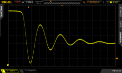
With 10n / 150n I could easily and perfectly damp the oscilation (quite visible on the screen) just by turning the trim.... once damped the trim read 137ohm.
If I remove the trimmer, oscilation is perfectly visible..... now with this setup I just connected the psu board (containing the rectifiers HEXFRED HFE 4060TB, and the 10000u smoothing cap) to the tx sec and oscilation disapeared. Instaling the trimer now does not change anything.... removing the psu board returns oscilation on the screen.
I know it is the psu board that damps the trafo..... the hexfreds are good fast soft recovery types and the caps are mundorfs 10.000u followed by 5kohm bleeders..... output of the psu is isolated (no connections) so the load is the bleeders alone.
As for connections, I first connected the trafo sec to quasimodo (shorted prim) and placed the probe on the output of the quasi pcb.
With 10n / 150n I could easily and perfectly damp the oscilation (quite visible on the screen) just by turning the trim.... once damped the trim read 137ohm.
If I remove the trimmer, oscilation is perfectly visible..... now with this setup I just connected the psu board (containing the rectifiers HEXFRED HFE 4060TB, and the 10000u smoothing cap) to the tx sec and oscilation disapeared. Instaling the trimer now does not change anything.... removing the psu board returns oscilation on the screen.
I know it is the psu board that damps the trafo..... the hexfreds are good fast soft recovery types and the caps are mundorfs 10.000u followed by 5kohm bleeders..... output of the psu is isolated (no connections) so the load is the bleeders alone.
MJ: If your rectifier current pulses are not narrow and steep...
RC: ... the load is the bleeders alone.
That sounds like it could be a plausible explanation. If you measure again after connecting high wattage load resistors that draw 2 amps per rail (or whatever your supply's max current is supposed to be), your stimulus "hammer" will deliver stronger and more vigorous "whacks", which might make the "bell" ring very strongly.
As a reminder, the Linear Audio article on soft recovery diodes says, "they all rang, including Schottkys and HEXFREDs". And, I hasten to point out, also including Fairchild Stealth-II ultra soft recovery rectifiers with a datasheet-guaranteed softness factor (tb/ta) of 4.2 ! But the measurements in that article obviously didn't use your transformer, which might have above average core losses / winding losses, and above average self-damping.
Last edited:
Well, I finally got around to using QUASIMODO. My first experience with an oscilloscope and it was much easier than I expected it to be.
I am using the same 'scope you used for your photographs.
With an 18 volts 400VA ANTEK transformer I measure 18.3R as the best value.
Seems there is no way to overdamp. On either side of this value things start looking funny. Of course, I probably missed something so I will be playing around with this to get some understanding.
I worried this value seemed low and then I tried a low VA HAMMOND split bobbin and this one liked approx 90R so I guess that satisfied me that my reading made sense.
For fun I tried substituting larger caps for Cx which did not make much difference, I mean I could not see a difference at all so I will be sticking with the suggested values for the capacitors.
Congratulations on your working Quasimodo!
It's a fun little exercise to figure out how to save the digital scope's screen image to a file on a USB thumb drive. Just difficult enough to be non-trivial, yet easy enough to start, finish, and succeed in less than an afternoon. Then when you've got it figured out, you'll be able to post images of your Quasimodo experiments (and other oscilloscope work!) here on the forum.
It's a fun little exercise to figure out how to save the digital scope's screen image to a file on a USB thumb drive. Just difficult enough to be non-trivial, yet easy enough to start, finish, and succeed in less than an afternoon. Then when you've got it figured out, you'll be able to post images of your Quasimodo experiments (and other oscilloscope work!) here on the forum.
Attachments
I noticed last evening that the trimpot I got is not very stable. The resistance goes screwy as I turn the screw - connected to my ohmmeter and turning the adjusting screw.
I inserted a 50R trimmer I had laying about and got much steadier readings. AND more importantly a different reading. Obviously i did not bother using this with the HAMMOND transformer. I know I have a "bad" trimmer. These things happen.
I thought I detected some heating of the 50R pot, is this possible or my imagination?
My question is: is there a reason for a 1K pot when I doubt anyone would need a value over 200R for snubbing? I am going to get a "full size" pot since I do not want to doubt the veracity of the trimmer. I am thinking 500R would allow finer adjustment.
Is there any reason not to use a lower value of resistance here? I cannot see one but that doesn't mean much.
- Home
- Amplifiers
- Power Supplies
- Simple, no-math transformer snubber using Quasimodo test-jig