Hi Pasi PPasi P said:Hi KLe,
Thanks for the tip but what is flyscreen 😕
I have thought that aluminium is not very good material for that purpose.
We have flyscreen's on our windows to stop flys, mosquito's, etc from getting into our houses when we open our windows 😉
I you do not have flyscreen then wire mesh is all you need.
Using Al, Cu, etc wire mesh will be just fine.

Hi,
an aluminium screen around the transformer will make an effective electric field screen if the joints and exit points are carefully detailed.
The electromagnetic fields will pass straight through aluminium as if it weren't there. You would need an iron based alloy enclosure to keep the transformer fields from affecting your other circuits. Steel would do or some would advocate mu metal (expensive).
I believe the ideal shield would be 400 grade Stainless Steel as it has a very high permittivity.
Where to 'find' it though.
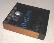
Greg sent me pics of a 'simple' stereo GB150D chassis he has near completion. It uses 300mm square steel base plate, steel perforated mesh cover and nice 'warm' wooden sides.
Seems corrupted. I'll try for another copy and post it later.
Where to 'find' it though.
Greg sent me pics of a 'simple' stereo GB150D chassis he has near completion. It uses 300mm square steel base plate, steel perforated mesh cover and nice 'warm' wooden sides.
Seems corrupted. I'll try for another copy and post it later.
Hi wooferman,
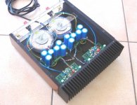
Cases are totally DIY. Aluminium sheets are cut with laser machine. Quite a hard job to do but then you can do exactly what you want
Heatsinks are from http://www.fischerelektronik.de/index.php?id=114&L=1
Cases are totally DIY. Aluminium sheets are cut with laser machine. Quite a hard job to do but then you can do exactly what you want
Heatsinks are from http://www.fischerelektronik.de/index.php?id=114&L=1
Greg has a tweak for his GB150D -
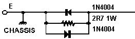
"For owners of the GB150D who may be interested in finessing the performance further I have a simple mod attached. This is a pre-filter for the CCS controlling input stage tail currents, and subsequently bias for the whole amplifier.
20db is a worthwhile improvement taking PSRR to ~ 110dB
This pre-filter is already built into the GB300D design. A small capacitor can be placed across the zener, of value 100nF up to 10uF, but larger values may cause a small turn-on thump. "
http://www.diyhifi.org/forums/viewtopic.php?p=13038#13038
I'll be trying this as soon as I finish mine.😀
Hi,
does your posted mod pre date or post date the 10uF cap shown under the PCB at the same location on Greg's mod sheet?
does your posted mod pre date or post date the 10uF cap shown under the PCB at the same location on Greg's mod sheet?
ska up and running
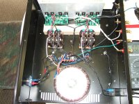
Finally got my gb150d running, only 30 minutes. Transformer is avel y23 500va, ended up 51v dc. Caps are 4 nippon chemi-con 63v 6800uf kmh 105c per side.
Heatsink is barely warm, my speakers are fostex ff165k, 94db in bib folded pipe.
early yet, will have to re-check bias and dc on output
Most people find these projects a breeze but I found it challenging
enough
cheers
doggy😎
Attachments
Hi,
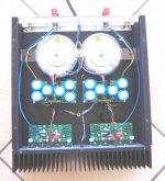
is that a wire I see before me?
From the central bolt between the smoothing caps to the terminal block I think I see a pussy cat, no, a bare copper wire link, am I correct?
I do not recommend you connect chassis (mains safety earth) directly to the audio ground. Are the two black wires the PCB ground reference?
How have you connected the smoothing cap common to the audio ground?
grounds
Hi Andrew,
Yes, that is a solid copper wire link from the ct junction to ground. The output grounds are also connected at the ct junction block. There is also a separate mains ac ground over to the side.
There is very little hum, you have te get close to the cones. The input signal wire is coaxial.
Where would you attach the board ref. ground?
cheers
doggy 🙂
Hi,
an audio ground could be formed from a brass bolt with a selection of brass nuts left floating above the chassis. An insulated tag strip could be used to support it and the disconnecting network that you may decide to fit.
Bring all your audio grounds to the brass bolt and attach them in groups to the bolt with a nut between each group:- Transformer & PSU, power (Large I including decoupling and speaker), signal (small I).
HiFiddle said:Greg has a tweak for his GB150D -
"For owners of the GB150D who may be interested in finessing the performance further I have a simple mod attached. This is a pre-filter for the CCS controlling input stage tail currents, and subsequently bias for the whole amplifier.
20db is a worthwhile improvement taking PSRR to ~ 110dB
This pre-filter is already built into the GB300D design. A small capacitor can be placed across the zener, of value 100nF up to 10uF, but larger values may cause a small turn-on thump. "
http://www.diyhifi.org/forums/viewtopic.php?p=13038#13038
I'll be trying this as soon as I finish mine.😀
I've done Gregs zener mod; had an hour or two to listen at highish and low levels.
There is a definite improvement in detail resolution and subjectively an impression of greater speed and slam; leading edges being better defined now. Its possible that backgrounds seem blacker now, but I'm less sure of this - there was never an issue here anyway.
I would say this mod slightly changes the character of the SKA, its still smooth and neutral, but a little more forward than before the mod. In my system this has actually improved the balance.
I'd recommend this one to all the builders, but try the standard way first for reference.
- Status
- Not open for further replies.
- Home
- Amplifiers
- Solid State
- Simple Killer Amp Constructor Thread