
Details:
Power X-former
Input 230Vac
Output
Rated:2x38Vac/300VA
Actual:2x43.2Vac (idle), 2x39.1Vac(full power, both channels)
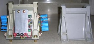
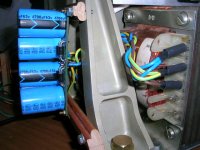
PSUs (GB150S) (each)
4x1N5408 diodes
6x4700uF/63V
2x0.1uFMKT
2x2700K/2W bleed resistors
DC out:2x57.5Vdc (idle), 2x47.1Vdc (full power)
Power X-former
Input 230Vac
Output
Rated:2x38Vac/300VA
Actual:2x43.2Vac (idle), 2x39.1Vac(full power, both channels)
PSUs (GB150S) (each)
4x1N5408 diodes
6x4700uF/63V
2x0.1uFMKT
2x2700K/2W bleed resistors
DC out:2x57.5Vdc (idle), 2x47.1Vdc (full power)
Attachments
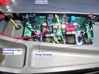
GB150D modules:
No R1 and C1.
No Bootstrap capacitors C4, C5.
Zener diode // 0.1uF modification.
Thermally coupled pairs of input transistors (Q1-Q2,Q3-Q4, Q5-Q6, Q7-Q8)
Standard supplied components, except of multiturn trimmers.
Bias set to +/-84mA (+/-840mV across test 10 Ohm resistors)
No R1 and C1.
No Bootstrap capacitors C4, C5.
Zener diode // 0.1uF modification.
Thermally coupled pairs of input transistors (Q1-Q2,Q3-Q4, Q5-Q6, Q7-Q8)
Standard supplied components, except of multiturn trimmers.
Bias set to +/-84mA (+/-840mV across test 10 Ohm resistors)
Attachments
Amplifier is to drive Jordan JX92S speakers (nominal 6 Ohm) in quarter wave enclosures (actual impedance 7-19 Ohm)
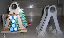
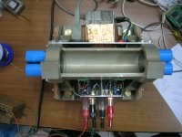
Open frame construction provides for good ventilation of amp. module’s components, cool running of PCB electrolytic caps, good heatsinking (high thermal inertia (mass) and adequate thermal radiating surface).
Later on I will provide a few measurements.
Regards
George
Open frame construction provides for good ventilation of amp. module’s components, cool running of PCB electrolytic caps, good heatsinking (high thermal inertia (mass) and adequate thermal radiating surface).
Later on I will provide a few measurements.
Regards
George
Attachments
gpapag said:So, a “what the f…. is this” was born.
My exact thought. 😀
Looks good though, in an industrial kind of way. I'm sure Greg will like it.
regards
Wow! Got my vote for unusual.
Do you plan to use the bootstrap capacitors?
How does it sound without them?
Do you plan to use the bootstrap capacitors?
How does it sound without them?
Hi gpapaggpapag said:So, a “what the f…. is this” was born. It is actually two GB150D modules, two PSUs (GB150S), one power x-former.
Excellent 😀
Now, what made you decide to do it that way, other than for people to say “what the f…. is this” 😎
When ready, you must post your listening impressions on the "listening" thread 🙂
thanks
KL
Hi Jacco,
tell us, MSRP?
Ampguru's whole PSRR philosophy revolves around the bootstrap caps.
I will be interested in the zero bootstrap option's sound.
tell us, MSRP?
Ampguru's whole PSRR philosophy revolves around the bootstrap caps.
I will be interested in the zero bootstrap option's sound.
MSRP= Manufactuer Suggested Retail Price.
Those fittings must have been filthy expensive.
(A300B4 = Airbus 300 type B4)
Those fittings must have been filthy expensive.
(A300B4 = Airbus 300 type B4)
AMP ART
KEWL!!-thinking outside the box; most likely this heatsink was a surplus piece.
cheers
Thor
KEWL=cool!
KEWL!!-thinking outside the box; most likely this heatsink was a surplus piece.
cheers
Thor
KEWL=cool!
Hi all
You would be right if I had to buy these fittings. But they were scraped some 10 years ago due to a mandatory modification. So I found them in the scrap metal bin (fittings were permanently marked –functionally damaged- so that they were not eligible for re-use)
The GB150U assembly instructions makes a note that removing bootstrap caps C4,C5 increases low order harmonic distortion making sound more tube-like. Now I play the JX92S speakers with a tube amplifier and I really enjoy it. The challenge for the GB150U amplifier is the sound of this tube amplifier (not necessarily “ideal” but the fine details, space, life and air of this tube amp are the ingredients of the sound that satisfy me) , so I want to make the comparison as fare as possible)
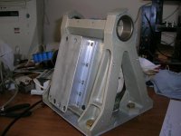
Although I would enjoy such a reaction, the reason was not to provoke people(in part, if I have to consider my wife among them!).
It was mostly logistics. The size of the x-former which I already had, dictated a large enclosure. I don’t like having the heat sinks inside a box. So heatsinks would be placed outside the enclosure. Then this large enclosure would be an almost empty enclosure. I hate this. I particularly hate empty sheet metal enclosures with the inevitable need to dump all these sheet metal possible vibrations. So, instead of utilizing a normal rectangular box (of which I have some), I had to fabricate one to my design. It had to be of a small footprint, extending mostly to it’s height in order to utilize some large vertical heatsinks that I already had. Searching my scrap metal bin for thick aluminum profile, I fell over these A300 fittings. It was a matter of a few days pencil work to decide that this fitting is a good choice. Rigidity and mass were particularly attractive. As the pencil work proceeded, details were arranged and formulation of an open-thermally attractive-frame, electrically safe and ergonomically justifiable design was accomplished. Industrial look came as a bonus (not another black box). I prefer to call it "form is to service function" That’s it.
Greg Erskine and doggy thank you.
HiFiddle, listening tests will take a while. I will report on the appropriate thread.
In this thread I will report technical issues only.
Regards
George
Jacco vermeulenThose fittings must have been filthy expensive.
You would be right if I had to buy these fittings. But they were scraped some 10 years ago due to a mandatory modification. So I found them in the scrap metal bin (fittings were permanently marked –functionally damaged- so that they were not eligible for re-use)
Andrew T.Ampguru's whole PSRR philosophy revolves around the bootstrap caps.
The GB150U assembly instructions makes a note that removing bootstrap caps C4,C5 increases low order harmonic distortion making sound more tube-like. Now I play the JX92S speakers with a tube amplifier and I really enjoy it. The challenge for the GB150U amplifier is the sound of this tube amplifier (not necessarily “ideal” but the fine details, space, life and air of this tube amp are the ingredients of the sound that satisfy me) , so I want to make the comparison as fare as possible)
KLENow, what made you decide to do it that way, other than for people to say “what the f…. is this”
Although I would enjoy such a reaction, the reason was not to provoke people(in part, if I have to consider my wife among them!).
It was mostly logistics. The size of the x-former which I already had, dictated a large enclosure. I don’t like having the heat sinks inside a box. So heatsinks would be placed outside the enclosure. Then this large enclosure would be an almost empty enclosure. I hate this. I particularly hate empty sheet metal enclosures with the inevitable need to dump all these sheet metal possible vibrations. So, instead of utilizing a normal rectangular box (of which I have some), I had to fabricate one to my design. It had to be of a small footprint, extending mostly to it’s height in order to utilize some large vertical heatsinks that I already had. Searching my scrap metal bin for thick aluminum profile, I fell over these A300 fittings. It was a matter of a few days pencil work to decide that this fitting is a good choice. Rigidity and mass were particularly attractive. As the pencil work proceeded, details were arranged and formulation of an open-thermally attractive-frame, electrically safe and ergonomically justifiable design was accomplished. Industrial look came as a bonus (not another black box). I prefer to call it "form is to service function" That’s it.
Greg Erskine and doggy thank you.
HiFiddle, listening tests will take a while. I will report on the appropriate thread.
In this thread I will report technical issues only.
Regards
George
Strange looking Amplifier, Temperature data
First some temperature measurement data.
They are unique to this particular open frame massive construction ( 8kg weight. All metal components -transformer included- are assembled with thermal compound in between).
Had a normal closed chassis been used, most locations would show elevated temperatures.
Due to vertical orientation of GB150U modules there is a temperature gradient of ~ 3 d.C between upper and lower edge of module. Had modules been oriented horizontally as usual, this gradient would not exist, temperature build-up would be higher though.
After amplifier operated for four hours with an output of 180mV rms on 6 Ohm dummy load (6.6 mW rms), both channels driven by 100Hz sinusoidal input, the following temperatures –in degrees Celcius-were recorded (data taken after 2 minutes thermal contact of 0.8mm x 0.8mm temp. probe with measuring point)
Ambient : 25.1
Heat sink (probe into drilled hole at the upper part of the fitting): 39.6
Output FET (upper): 44.7
Output FET (lower): 43.3
Electrolytic cap close to output FET, (upper): 41.7
Electrolytic cap close to output FET, (lower): 38.1
Input transistor pair, (upper): 46.3
Input transistor pair, (lower): 43.4
R24 (upper): 56.6
R26 (lower): 55.1
PSU pcb: 30.4
PSU electrolytic caps : 29.2
PSU bleed resistors: 35.3
Power x-former core: 40.8
With amplifier already warm (case temp.~38) and after an hour operation (100Hz sinusoidal input, both channels driven) at 1W rms on 6 Ohm dummy load:
Ambient : 25.4
Heat sink (probe into drilled hole at the upper part of the fitting): 53.8
Output FET (upper): 64.8
Power x-former core: 44
Same temperatures (+/- 1 d.C) were recorded during high and full power testing (2 minutes full power 3-4 minutes idle for around 20 minutes)
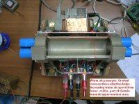
Warm air channeling (chimney effect) increases air circulation achieving long term temperature stability. Adequate aluminum thermal mass keep things under control for the short run (transients).
First some temperature measurement data.
They are unique to this particular open frame massive construction ( 8kg weight. All metal components -transformer included- are assembled with thermal compound in between).
Had a normal closed chassis been used, most locations would show elevated temperatures.
Due to vertical orientation of GB150U modules there is a temperature gradient of ~ 3 d.C between upper and lower edge of module. Had modules been oriented horizontally as usual, this gradient would not exist, temperature build-up would be higher though.
After amplifier operated for four hours with an output of 180mV rms on 6 Ohm dummy load (6.6 mW rms), both channels driven by 100Hz sinusoidal input, the following temperatures –in degrees Celcius-were recorded (data taken after 2 minutes thermal contact of 0.8mm x 0.8mm temp. probe with measuring point)
Ambient : 25.1
Heat sink (probe into drilled hole at the upper part of the fitting): 39.6
Output FET (upper): 44.7
Output FET (lower): 43.3
Electrolytic cap close to output FET, (upper): 41.7
Electrolytic cap close to output FET, (lower): 38.1
Input transistor pair, (upper): 46.3
Input transistor pair, (lower): 43.4
R24 (upper): 56.6
R26 (lower): 55.1
PSU pcb: 30.4
PSU electrolytic caps : 29.2
PSU bleed resistors: 35.3
Power x-former core: 40.8
With amplifier already warm (case temp.~38) and after an hour operation (100Hz sinusoidal input, both channels driven) at 1W rms on 6 Ohm dummy load:
Ambient : 25.4
Heat sink (probe into drilled hole at the upper part of the fitting): 53.8
Output FET (upper): 64.8
Power x-former core: 44
Same temperatures (+/- 1 d.C) were recorded during high and full power testing (2 minutes full power 3-4 minutes idle for around 20 minutes)
Warm air channeling (chimney effect) increases air circulation achieving long term temperature stability. Adequate aluminum thermal mass keep things under control for the short run (transients).
Attachments
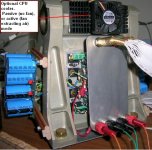
With amplifier already warm (case temp.~38) and after one and two hours playing classic music at higher than my normal listening levels through the JX92S speakers at the living room (ambient temp 25 +/-0.5d.C), heat sink temperature did not raise above 41 d. C
In case that listening tests define need for increasing bias-hence operating temperatures- extra cooling is possible
In case that listening tests define need for increasing bias-hence operating temperatures- extra cooling is possible
Attachments
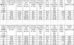
Strange looking Amplifier, Electrical data
Initially, tests were accomplished by driving amplifier with 100Hz sinusoidal signal.
Upper table produced.
System Power efficiency results were showing something is wrong.
Power drawn from the utility (X-former input power) at high power settings is not adequate to support the amplifier measured output power. Running tests again did not change the results.
I run the test again, this time by driving the amplifier with 10 Khz sinusoidal signal.
Lower table produced.
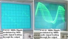
Now the laws of thermodynamics are much more preserved. What is happening? The only possible explanation I can think of, is due to PSU ripple resonating currents. DC ripple for full wave rectification occurs at twice the utility AC frequency, in my case 50Hz x 2 = 100Hz. When amplifier drive frequency coincides with this frequency, DC Ripple modulates heavily, especially at high power operation.
Initially, tests were accomplished by driving amplifier with 100Hz sinusoidal signal.
Upper table produced.
System Power efficiency results were showing something is wrong.
Power drawn from the utility (X-former input power) at high power settings is not adequate to support the amplifier measured output power. Running tests again did not change the results.
I run the test again, this time by driving the amplifier with 10 Khz sinusoidal signal.
Lower table produced.
Now the laws of thermodynamics are much more preserved. What is happening? The only possible explanation I can think of, is due to PSU ripple resonating currents. DC ripple for full wave rectification occurs at twice the utility AC frequency, in my case 50Hz x 2 = 100Hz. When amplifier drive frequency coincides with this frequency, DC Ripple modulates heavily, especially at high power operation.
Attachments
A picture from the oscilloscope screen is attached.
Picture shows voltages, the amplitude of which can not adequately explain the discrepancy. Probably currents are a different story.
If someone has experienced something similar, I would be happy to know.
Picture shows voltages, the amplitude of which can not adequately explain the discrepancy. Probably currents are a different story.
If someone has experienced something similar, I would be happy to know.
Attachments
Anyway, the second table (attachment on post#318) provides realistic results.
X-former regulation is very good.
[regulation= (100*(Vmax-Vmin))/Vmin ]. Values smaller than 15% are very good.
PSU is quite beefy. It supports 190+ Wrms power, both channels driven.
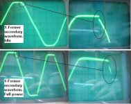
PSU ripple amplitude is good, indicating adequate filter capacitance. At the same time, capacitance charging currents do not produce any ugly ringing at the x-former secondary (see picture)
Regards
George
X-former regulation is very good.
[regulation= (100*(Vmax-Vmin))/Vmin ]. Values smaller than 15% are very good.
PSU is quite beefy. It supports 190+ Wrms power, both channels driven.
PSU ripple amplitude is good, indicating adequate filter capacitance. At the same time, capacitance charging currents do not produce any ugly ringing at the x-former secondary (see picture)
Regards
George
Attachments
- Status
- Not open for further replies.
- Home
- Amplifiers
- Solid State
- Simple Killer Amp Constructor Thread