I take it you mean you have 4 toroids of 300VA per channel, times 2 is 8 ?
I'm not able to switch on a 1000VA without a softstart on a 16amp fuse, let alone something bigger, and i have much bigger ones.
Switching on 3 toroids of 300VA doesn't exactly equal one of 1000VA, but you'll are likely to loose the main fuse just the same.
Otherwise 4 toroids simultaneously will.
So either softstarters for the whole batch or a sequential starter, otherwise no go !
Hi,
as Jacco warned, two 300VA toroids for four GB150 is asking too much. Each GB300 will need more than 300VA on it's own.
I hope we misread your post.
Ampguru recommends 200VA for each GB150 (his diagram shows 150VA to 300VA for each GB150).
and 400VA to 500VA for each GB300. That adds up to 1600VA minimum.
I can confirm that a single GB150 runs well on 300VA, 35+35Vac with +-30mF per channel on a single snubbered bridge diode.
If you want to run the new higher recomendation 75mA per output device then use a sink at least as big as his new size. i.e. 0.8C/W for 8ohm and 0.65C/W for 4ohm.
If the power switch is controlling more than 300VA then I would recommend soft starting.
Thanks for your input, jacco and AndrewT!
Just to clarify, the amps are for a stereo pair of quad-amplified, 4-driver, 3-way active Linkwitz Orion speakers, so 8 channels in all, implemented as 2 four-channel boxes.
Each box is planned to contain:
Four GB150D amplifier modules
Two GB300S power supply modules
Two 300VA/35V transformers
Now I'm confused. Greg told me that 300VA is the perfect choice for this config, but now you guys are telling me otherwise. The Orions, being dipoles, can be driven to full SPL using little more than 60W/driver, so for now I don't really need the full 150W, but I did tell Greg that I wanted full power from the GB150D's in case I ever wanted to use the amps for HT instead.
The two bass amps in each cabinet amplify excatly the same signal. Would it make sense to invert input and output on one of them so they draw current from different rails of the power supply? Or would it make more sense to run bass1+midrange off one GB300S and bass2+treble off the other?
I've assembled all the PCB's, purchased the transformers and am waiting for the cabinets to arrive from Italy.
Are you certain that 300VA is too small? Should I perhaps have another word with Greg before I proceed?
Can you recommend a good softstart module, DIY or otherwise?
Thanks again!
I have running stereo amp with 320VA, 36V. This works great for me. Will be building another stereo amp with 300VA, 35V.
Hi,
your proposal to run 2*gb300 + 4*gb150 from 2*300VA will work, but not well.
It is normal to use transformer VA~=1.5*output power.
Some claim advantage in going even bigger.
You can manage with less VA if you compensate to help the bass response. I find that the usual recommendation of 2 to 3mF/Apk of output current works well using 1.5*Watts. If you increase this to double you can get reasonable performance from a half size transformer.
However you are proposing to use one third transformer power.
Your total output power is 1200watts your total transformer power should be 1800VA to 2000VA. You will lose some performance by reducing to 1000VA and doubling the capacitance.
There is one saviour.
The amplifiers will all be loaded with narrow band loads and fed from narrow band signals.
The chance of ALL the amps drawing maximum power from the PSU at the SAME time and in the SAME phase are almost zero.
Here's my solution.
Build a rectifier and smoothing bank for EACH amplifier. Select the size of smoothing bank and type of smoothing capacitor to suit the signal range each amplifier is handling. i.e big and beefy for the bass and smaller and faster for the mid and even faster (exclusively paper in oil or polypropylene) for the treble.
coolbiz said:run bass1+midrange off one GB300S and bass2+treble off the other
This would seem the logical choice to me, 1 of the 10 inchers on 1 PS/300VA would result in a more balanced loading of the transformers and capacitors.
2 times 300VA = 600VA, more than the Orions will ever be able to munch.
The load on an amplifier in an active system is far more pleasant, means also the load on the powersupplies is more friendly.
If you ever split them up i'd add 2 extra 300VA's, 1 per amp.
I would not invert 1 of the Bass amps, bad choice.
The choice in softstarters is so various, you can go from a complete Hypex version to a DIY schematic posted by Quasi on his quasicomplementary design thread.
Orions are very nice.
GB300S is a power supply module for one GB300D or two GB150D.AndrewT said:your proposal to run 2*gb300 + 4*gb150 from 2*300VA will work, but not well.
I believe coolbiz wants to run for GB150 amps from two GB300S power supplies using two 300VA toroids.
Seen more than a few active loudspeakers that had only 1 transformer.
IIRC, a GB300 powersupply has 10 small 4700uF electrolytics, that's 47000uF.
94000uF and 2 times 300VA is plenty overkill for an active loudspeaker like the Orion.
Mr Ball isn't exactly advising to go cheap.
IIRC, a GB300 powersupply has 10 small 4700uF electrolytics, that's 47000uF.
94000uF and 2 times 300VA is plenty overkill for an active loudspeaker like the Orion.
Mr Ball isn't exactly advising to go cheap.
Suggestion
If the amps are from Greg Ball, ask him. He has great
suggestions and support. gregmball@hotmail.com
Also "Vetran" had a remote control unit he is building in the
"Chip Amp" section.
If the amps are from Greg Ball, ask him. He has great
suggestions and support. gregmball@hotmail.com
Also "Vetran" had a remote control unit he is building in the
"Chip Amp" section.
Hi guys,
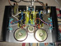
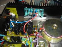
I've been reading this thread for quite a while. It was reading this that made me decide on the GB150's in the first place. We'll, I've had mine run for quite a while now, although the case is not complete yet (I'm not into metalwork too much, so it's been painfull). I've attached a pic showing how far I am, but there is still quite some work left. Basically, I just bought 2 modules to see how it would sound, before splurging on buying the rest to complete my HT setup. As anyone who has built these can attest, these things sound FANTASTIC!!!!! I suppose it goes without saying that I'll be purchasing more of these to complete the system!!
I'm not one for the fancy audiophile speak, but all I can say is that this is THE most fulfilment I have had with a DIY project in a REALLY long time. All the comments in previous posts are spot on, regarding the SQ of these modules.
By the way, I write embedded software for a living, so my amp just HAD to be microprocessor controlled. It's not complete yet, but it'll get there. I kinda got side-tracked listening to the thing instead of working on it. Also, I added the ability to have DC protect and anti-thump, plus balanced drive.
Anyways, just thought I'd share
Cheers
Gert
I've been reading this thread for quite a while. It was reading this that made me decide on the GB150's in the first place. We'll, I've had mine run for quite a while now, although the case is not complete yet (I'm not into metalwork too much, so it's been painfull). I've attached a pic showing how far I am, but there is still quite some work left. Basically, I just bought 2 modules to see how it would sound, before splurging on buying the rest to complete my HT setup. As anyone who has built these can attest, these things sound FANTASTIC!!!!!
I suppose it goes without saying that I'll be purchasing more of these to complete the system!!I'm not one for the fancy audiophile speak, but all I can say is that this is THE most fulfilment I have had with a DIY project in a REALLY long time. All the comments in previous posts are spot on, regarding the SQ of these modules.
By the way, I write embedded software for a living, so my amp just HAD to be microprocessor controlled. It's not complete yet, but it'll get there. I kinda got side-tracked listening to the thing instead of working on it. Also, I added the ability to have DC protect and anti-thump, plus balanced drive.
Anyways, just thought I'd share
Cheers
Gert
Attachments
Hello Gert,
Couple of q's:
I am also in SA; Where did you buy your transformers, what are their specs (VA and AC) and what did they cost?
What rectifying diodes are you using on the power supply?
What is the board with the relay on it on each channel and did you buy it or design it?
What is the board down the center?
Have you built a gainclone before and if so, how does this compare soundwise?
Thanks
Ryan
Please take a look at this schematic that i found at http://users.swing.be/edwinpaij/ampli_mosfet_simple.htm and tell me your opinion(or anyone in this forum),if it can be work well, at least it seems to be a decent circuit, with more controls to adjust it (I don´t want to explode mosfet´s because are more expensive that the BJT´s).
Even in this page there is an upgrade version of this amp with some components but that.
Also if somebody build it that write a comment
Thanks to all
Even in this page there is an upgrade version of this amp with some components but that.
Also if somebody build it that write a comment
Thanks to all
Attachments
Hi Ryan,
Whew, I'll answer the q in order
1. Transformers are from Toroidal Technologies, they are 225VA each with 35-0-35V secondaries. They cost around R220 ex VAT. Tel number is 011 615 7245, talk to Jan
2. I can't remember the rectifier diodes part number, I'll check at home. They are TO220, around 1kV and about 10A or so.
3. That board is the anti thump relay and it will eventually have all the balanced line receiver parts on it. The anti thump is my own design, controlled by the MCU board in the middle and the balanced line circuit is pretty standard. Don't have schematics with me.
4. Board down the centre is the MCU board (I know, it's overkill!!)
5. Nope, I haven't built a gainclone. I suppose I've never liked chipamps, personal thing really! The SKA is not THAT expensive in kit form, so what have you got to lose. At least that's what I figured and it turned out quite well.
Cheers
Gert
Hi Gbyleveldt,
You have some pretty good skills showing through there.
Can I make a couple of suggestions.
1. the input coax runs a bit close to the PSU to amp power cables and they are parallel. Try re-routing the input coax near the case edges.
2. the two bolt fixing for the output FETS leaves the strong possiblity of flex in the Aluminium bar allowing more force on the outer FETs and considerably less force on the inner FETs. In the extreme the inner FETS could have no clamping force if the securing bolts were tightened excessively.
One extra bolt in the middle removes most of the problem.
Would you like to share the monitoring schematics with us?
Is the software easy to download if sharing?
What level of expertise do we need if we were to follow down a similar route?
Hi Gertgbyleveldt said:Hi guys,
I've been reading this thread for quite a while. It was reading this that made me decide on the GB150's in the first place... As anyone who has built these can attest, these things sound FANTASTIC!!!!!
I'm not one for the fancy audiophile speak, but all I can say is that this is THE most fulfilment I have had with a DIY project in a REALLY long time. All the comments in previous posts are spot on, regarding the SQ of these modules.
By the way, I write embedded software for a living, so my amp just HAD to be microprocessor controlled. It's not complete yet, but it'll get there. I kinda got side-tracked listening to the thing instead of working on it. Also, I added the ability to have DC protect and anti-thump, plus balanced drive.
Cheers
Gert
Way to go ... looks fantastic 😀
Keep us posted of your progress 😎
Microprocessor controlled ... nice one 😎
thanks
KL
@ AndrewT
Thanx for your suggestions, much appreciated! Regarding the alu bar, I put small pieces of rubber between the bar and the fets, so creating even pressure over all the fets, but I agree that your's is a better idea, I'll definately incorporate that. Why didn't I think of that
I'm still busy finalising the DC protect side, it is a little board that plugs into the CPU board. I'll try have a draft up a bit later. I haven't had TOO much time to play with the software, I spent most of my time on the pre-amp software (another project). Not all the safety features are running yet, I just couldn't wait to hear the thing, so I took a temporary shortcut!
I do most of my software in C running on AVR CPU's. They're VERY easy to use. I will gladly share the code and schematics once I'm done 😉
@KLe
Thanx for your nice comments, I'll keep you posted closer to completion.
Gert
Re: Suggestion
That's reassuring to know. Thanks!
Thanks for advice.
I finally found a source for a suitable power switch, so I'll try to do without the softstart for now.
Correctemundo!
That is an excellent suggestion, ppcblaster!
My original question concerned finding a suitable power switch for the amps and was not about power supply configuration, which I requested the assistance of this knowledgable forum rather than bothering Greg.
This thread had me worried for a second that I had misinterpreted Greg's advice.
I am happy to report that Greg, helpful as always, has confirmed to me that one 300VA and GB300S supply for the bass amps and one 300VA and GB300S for mid
and treble amps is indeed the recommended configuration, and that 600VA is fine and more than adequate, when you consider average power demand here per channel would be < 50W at idle and < 100W under typical music demand.
Thanks to ppcblaster, AndrewT, jacco and yggdrasil for valuable input. Much appreciated!
yggdrasil said:I have running stereo amp with 320VA, 36V. This works great for me. Will be building another stereo amp with 300VA, 35V.
That's reassuring to know. Thanks!
jacco vermeulen said:
...
I would not invert 1 of the Bass amps, bad choice.
The choice in softstarters is so various, you can go from a complete Hypex version to a DIY schematic posted by Quasi on his quasicomplementary design thread.
Orions are very nice.
Thanks for advice.
I finally found a source for a suitable power switch, so I'll try to do without the softstart for now.
yggdrasil said:
GB300S is a power supply module for one GB300D or two GB150D.
I believe coolbiz wants to run for GB150 amps from two GB300S power supplies using two 300VA toroids.
Correctemundo!
ppcblaster said:If the amps are from Greg Ball, ask him. He has great
suggestions and support. gregmball@hotmail.com
...
That is an excellent suggestion, ppcblaster!
My original question concerned finding a suitable power switch for the amps and was not about power supply configuration, which I requested the assistance of this knowledgable forum rather than bothering Greg.
This thread had me worried for a second that I had misinterpreted Greg's advice.
I am happy to report that Greg, helpful as always, has confirmed to me that one 300VA and GB300S supply for the bass amps and one 300VA and GB300S for mid
and treble amps is indeed the recommended configuration, and that 600VA is fine and more than adequate, when you consider average power demand here per channel would be < 50W at idle and < 100W under typical music demand.
Thanks to ppcblaster, AndrewT, jacco and yggdrasil for valuable input. Much appreciated!
coolbiz said:I finally found a source for a suitable power switch, so I'll try to do without the softstart for now.
Unless you mean to switch-On one powersupply after the other that better be one H... of a switch !
The inrush current of a 300VA combined with 10 electrolytic capacitors in parallel is pretty powerfull.
M.VdV who designs for Plitron did an article long time ago on toroid PS inrush current levels, his current/time graph was impressive.
- Status
- Not open for further replies.
- Home
- Amplifiers
- Solid State
- Simple Killer Amp Constructor Thread