Strange looking Amplifier Crosstalk Correction
Question: How can I please Mr. float and Mr. AndrewT in respect to the crosstalk data presented on post #324 ?
Answer 1: By manipulating the data (easy but unethical).
Answer 2: By changing the point where I attach the ground of the oscilloscope probes (easier but self- humiliating to admit) .
Well, I sat my a… down to repeat the crosstalk measurement, I said: These people must know better.
I installed the shorting RCA plug on L channel's input.
I connected the oscillator to the R channel's input.
I connected the dummy loads, one on each channel output.
I attached the channel 1 oscilloscope probe on the “red” L output plug and it’s ground crocodile clip on the “black” L output plug.
I attached the channel 2 oscilloscope probe on the “red” R output plug and it’s ground crocodile clip on the “black” R output plug.
I started the test.
The 1st measurement was providing almost the same data as on post# 324 .
As I was observing on the channel 1 of the oscilloscope the residues of the undriven L channel (~10mVpp sinusoid), the mobile phone rang.
I moved my hand to answer the call and I disconnected one of the probe’s ground crocodile clips.
While I was talking to the phone, I observed on the screen that the 10mVpp sinusoid of the L channel had turned to a straight line (0Vpp).
After the phone, I reconnected the crocodile clip.
Everything in order. The 10mVpp sinusoid of the L channel was back again.
It was that moment, that I felt pazzled. For, the disconnected crocodile clip belonged to the driven R channel. Not to the shorted L channel, the residues of which I was observing.
The mistake in a few words (float you were right: It was a measurement issue!):
One probe’s ground was noisy (attached to the driven channel’s speaker return), modulating (?) the signal of the other channel by this noise.
Attaching both probes crocodile clips on a low noise ground, made things look as they really were, i.e. much better.
Below you will see the new crosstalk data.
Thanks goes to AndrewT and float, the persistence of whom made me try the test again.
Thanks goes also to the friend of mine who called me at the right moment.
Thanks goes to me as well, who had the vision to place the mobile phone at the right place.
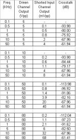
Test accomplished by shorting the input of one channel and driving only the other channel.
The output of both channels (loaded by 6 Ohm dummy load) recorded.
Crosstalk (dB)=20*log (shorted-input channel output / driven channel output).
Observation 1: Crosstalk drops off considerably at higher frequencies.
Observation 2: Crosstalk is independent of power output
Again, my apologies for the misinformation.
Greg, believe me. It is not intentional!
Regards
George
Question: How can I please Mr. float and Mr. AndrewT in respect to the crosstalk data presented on post #324 ?
Answer 1: By manipulating the data (easy but unethical).
Answer 2: By changing the point where I attach the ground of the oscilloscope probes (easier but self- humiliating to admit) .
Well, I sat my a… down to repeat the crosstalk measurement, I said: These people must know better.
I installed the shorting RCA plug on L channel's input.
I connected the oscillator to the R channel's input.
I connected the dummy loads, one on each channel output.
I attached the channel 1 oscilloscope probe on the “red” L output plug and it’s ground crocodile clip on the “black” L output plug.
I attached the channel 2 oscilloscope probe on the “red” R output plug and it’s ground crocodile clip on the “black” R output plug.
I started the test.
The 1st measurement was providing almost the same data as on post# 324 .
As I was observing on the channel 1 of the oscilloscope the residues of the undriven L channel (~10mVpp sinusoid), the mobile phone rang.
I moved my hand to answer the call and I disconnected one of the probe’s ground crocodile clips.
While I was talking to the phone, I observed on the screen that the 10mVpp sinusoid of the L channel had turned to a straight line (0Vpp).
After the phone, I reconnected the crocodile clip.
Everything in order. The 10mVpp sinusoid of the L channel was back again.
It was that moment, that I felt pazzled. For, the disconnected crocodile clip belonged to the driven R channel. Not to the shorted L channel, the residues of which I was observing.
The mistake in a few words (float you were right: It was a measurement issue!):
One probe’s ground was noisy (attached to the driven channel’s speaker return), modulating (?) the signal of the other channel by this noise.
Attaching both probes crocodile clips on a low noise ground, made things look as they really were, i.e. much better.
Below you will see the new crosstalk data.
Thanks goes to AndrewT and float, the persistence of whom made me try the test again.
Thanks goes also to the friend of mine who called me at the right moment.
Thanks goes to me as well, who had the vision to place the mobile phone at the right place.
Test accomplished by shorting the input of one channel and driving only the other channel.
The output of both channels (loaded by 6 Ohm dummy load) recorded.
Crosstalk (dB)=20*log (shorted-input channel output / driven channel output).
Observation 1: Crosstalk drops off considerably at higher frequencies.
Observation 2: Crosstalk is independent of power output
Again, my apologies for the misinformation.
Greg, believe me. It is not intentional!
Regards
George
Attachments
Well done George, thats more like it!😎
Thanks again for your efforts; I think these are very worthwhile measurements - I think its harder to measure amplifiers than it is to build them.😀
All the best
Thanks again for your efforts; I think these are very worthwhile measurements - I think its harder to measure amplifiers than it is to build them.😀
All the best
Andrew,
Seeing as George is apologising let me chime in also - my recollection of the C2 cap value was way off - by 200 in fact - original value supplied with the board was in fact 1nF not 200nF as I stated.
Sorry about the mistake.
Also seems as output impedance is difficult to determine a preamp or buffer is pretty much necessary to achieve controlled freq response?
John
Hi John,
don't let a few decimal places overly concern you. As long as checking uncovers the error.
In my real job every calculation has to be independantly checked by a competent person, the process being specifically designed to eliminate errors.
What I can say is that the source to input circuit must be designed competently whether it is buffered or passive.
The design for passive is more demanding but potentially better sounding if the correct choices of component VALUES are made.
Unbuffered can be made to work very well it's just easier to go buffered.
don't let a few decimal places overly concern you. As long as checking uncovers the error.
In my real job every calculation has to be independantly checked by a competent person, the process being specifically designed to eliminate errors.
buffer is ideal for optimising the impedances but for many listeners it introduces an extra level of amplification that interferes with the quality of the final output. Choose your own priorties.Also seems as output impedance is difficult to determine a preamp or buffer is pretty much necessary to achieve controlled freq response
What I can say is that the source to input circuit must be designed competently whether it is buffered or passive.
The design for passive is more demanding but potentially better sounding if the correct choices of component VALUES are made.
Unbuffered can be made to work very well it's just easier to go buffered.
Hi Qp,
that's an impressive set of figures in post342.
Were you confident of trying 80Vpp into 6r @ 50kHz? That's 133W!
How long did you run each test for?
I use a -20db switch that I can flick across for the higher power reading. Usually only for a very few seconds.
that's an impressive set of figures in post342.
Were you confident of trying 80Vpp into 6r @ 50kHz? That's 133W!
How long did you run each test for?
I use a -20db switch that I can flick across for the higher power reading. Usually only for a very few seconds.
Those are great measurements gpapag. I would have expected better crosstalk. Greg measured around 80dB at 10KHz with mine.
But have you started to listen yet?
But have you started to listen yet?
HiFiddle
1. Greg's more controlled testing environment.
2. Greg's better test equipment.
3. Greg’s better technical knowledge on the subject.
3. Greg's (your amplifier’s) better grounding arrangement.
The first and second are very likely a possibility.
The third is to be taken for granted.
As for the fourth, please note that all the measurements I have reported so far were done with both PCBs having their star earth connected directly to chassis ground.
After AndrewT strong opposition to my grounding scheme, I had to rethink. Proof that AndrewT is correct, came during some high-power, difficult-load driving tests (more of this on another post). After these tests, I inserted the 2.7 Ohm//1N4001 between each PCB and chassis.
Now I have to re-run some of the tests to see if something has changed significantly. I will let you know.
Hi AndrewT
Just mind the two 3.15A fuses, the two 10 Ohm test resistors and if you go into real trouble, R27 as well.
At 80Vpp amplifier is well into clipping. I run it at this level to see if distortion products would show up in the crosstalk measurement. They didn't.
This (W average) is indeed the correct notation for expressing power delivered to the load.
I used Wrms (Wrms=(SQRT(1.5)*W average), which is probably a misnomer.
This -20db switch is a very clever idea. I think I will adopt it. Thanks
Hi float
After testing is over, what is left is build something else.
I only try to spend as less as possible.
For valuable testing hints and in-depth analysis of measurement faults, mind this book: "Audio Measurements" by Norman H. Crowhurst, reprinted and distributed by Audio Amateur Press
Regards
George
There may be at least four reasons for this difference:Those are great measurements gpapag. I would have expected better crosstalk. Greg measured around 80dB at 10KHz with mine.
1. Greg's more controlled testing environment.
2. Greg's better test equipment.
3. Greg’s better technical knowledge on the subject.
3. Greg's (your amplifier’s) better grounding arrangement.
The first and second are very likely a possibility.
The third is to be taken for granted.
As for the fourth, please note that all the measurements I have reported so far were done with both PCBs having their star earth connected directly to chassis ground.
After AndrewT strong opposition to my grounding scheme, I had to rethink. Proof that AndrewT is correct, came during some high-power, difficult-load driving tests (more of this on another post). After these tests, I inserted the 2.7 Ohm//1N4001 between each PCB and chassis.
Now I have to re-run some of the tests to see if something has changed significantly. I will let you know.
Yes and no.But have you started to listen yet?
Hi AndrewT
This amplifier is robust. Trust me. The only thing I havn' done to it (yet) is to disconnect the input during full power.Hi Qp,
that's an impressive set of figures in post342.
Were you confident of trying 80Vpp into 6r @ 50kHz?
Just mind the two 3.15A fuses, the two 10 Ohm test resistors and if you go into real trouble, R27 as well.
At 80Vpp amplifier is well into clipping. I run it at this level to see if distortion products would show up in the crosstalk measurement. They didn't.
Now that you mention it, it is indeed 133W. (W average= Vrms^2/R = ((Vpp/2.83)^2)/RThat's 133W!
This (W average) is indeed the correct notation for expressing power delivered to the load.
I used Wrms (Wrms=(SQRT(1.5)*W average), which is probably a misnomer.
Well, the fastest I can make it, is 15 seconds for each measurement. And if I have to take a screen photo as well, then it is 20 seconds (I had it count for you).How long did you run each test for?
This -20db switch is a very clever idea. I think I will adopt it. Thanks
Hi float
After building it, what is left is testing it.I think its harder to measure amplifiers than it is to build them.
After testing is over, what is left is build something else.
I only try to spend as less as possible.
For valuable testing hints and in-depth analysis of measurement faults, mind this book: "Audio Measurements" by Norman H. Crowhurst, reprinted and distributed by Audio Amateur Press
Regards
George
Hi,
I think a 1n400x is too small. A high current fault current could be thousands of amps.
The diode needs to survive long enough for the fuse to blow.
I have just built up a diode bridge for this duty.
Using both sides of a 25A power rectifier. It will have a peak capacity into the many hundreds of amps.
Strange looking Amplifier Crosstalk after Ground connection changed.
Hi all
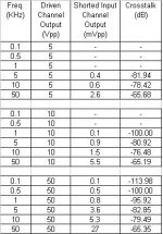
After changing the way that the star earth point of each PSU is connected to chassis ground (i.e. from plane wire to 2.7 Ohm with 2 antiparallel 1N4004), I tested again for crosstalk. There is a certain improvement.
Attached is the new data. In some shells on the third column, there is no data but a dash. This means that the signal was below 0.1mVpp ( my oscilloscope has 1mV/division sensitivity).
Test accomplished by shorting the input of one channel and driving only the other channel.
The output of both channels (loaded by 6 Ohm dummy load) recorded.
Crosstalk (dB)=20*log (shorted-input channel output / driven channel output).
Observation 1: Crosstalk drops off considerably at higher frequencies.
Observation 2: Crosstalk is independent of power output
Regards
George
Hi all
After changing the way that the star earth point of each PSU is connected to chassis ground (i.e. from plane wire to 2.7 Ohm with 2 antiparallel 1N4004), I tested again for crosstalk. There is a certain improvement.
Attached is the new data. In some shells on the third column, there is no data but a dash. This means that the signal was below 0.1mVpp ( my oscilloscope has 1mV/division sensitivity).
Test accomplished by shorting the input of one channel and driving only the other channel.
The output of both channels (loaded by 6 Ohm dummy load) recorded.
Crosstalk (dB)=20*log (shorted-input channel output / driven channel output).
Observation 1: Crosstalk drops off considerably at higher frequencies.
Observation 2: Crosstalk is independent of power output
Regards
George
Attachments
DC Protect
Hi guys,
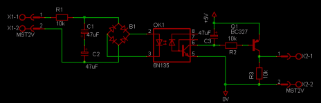
I have been working on the CPU for my amp over the weekend and I'm at the DC protect part now. Attached is an image of what I have so far. It is required to use an optocoupler to prevent the amp grounds interfering with the CPU grounds. I have tested this with on breadboard sofar and I get reliable triggering at around 4Hz at 20VRMS. I'm testing on a signal gen and oscilloscope, haven't fed an amp into it, so I'll probably have to play with the size of the caps if it triggers prematurely in use. The ouput of this sticks high when triggered, this is monitored by the micro to immediately release the relay of triggered.
What do you guys think? Is this analogue blasphemy?! Bear in mind that I'm better at things digital than analogue
If this is done, it's over to the DS1820 temperature sensor interface for the amps. (I know, this is overengineering but a very interesting excersize😀 ) I'll then post code for whoever is interested...
Cheers
Gert
Hi guys,
I have been working on the CPU for my amp over the weekend and I'm at the DC protect part now. Attached is an image of what I have so far. It is required to use an optocoupler to prevent the amp grounds interfering with the CPU grounds. I have tested this with on breadboard sofar and I get reliable triggering at around 4Hz at 20VRMS. I'm testing on a signal gen and oscilloscope, haven't fed an amp into it, so I'll probably have to play with the size of the caps if it triggers prematurely in use. The ouput of this sticks high when triggered, this is monitored by the micro to immediately release the relay of triggered.
What do you guys think? Is this analogue blasphemy?! Bear in mind that I'm better at things digital than analogue
If this is done, it's over to the DS1820 temperature sensor interface for the amps. (I know, this is overengineering but a very interesting excersize😀 ) I'll then post code for whoever is interested...
Cheers
Gert
Attachments
Hi,
470mS could be about right for a single pole filter. Maybe a bit bigger.
Will it trigger if maximum voltage (28vac to 40Vac) 20Hz signal is applied?
Can the detector work if R1 value is raised?
Normally 100k and a few uF are used to trigger a transistor switch rather than your opto isolator.
What happens to the detector if sustained DC is applied equal to the PSU rail voltage?
Hi Andrew
The filter seems to have a surprisingly sharp rolloff at 20VRMS. I have measured it at 5Hz and it doesn't trigger, but triggers at 4Hz. I have not tried a higher voltage yet (my sig gen only goes up to 20VRMS) and do not feel like calculating it yet, but I should be OK for 20Hz at full output. I'll do the calcs bit later to be sure.
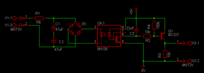
I wouldn't raise the value of R1, as I cannot get enough current into the opto to trigger reliably at lower voltages (I want it to be reasonably sensitive). I agree that it is a bit unusual using this circuit but I'm kinda forced becuase I want the grounds to be isolated.
I should be OK up to 140vpk for that opto with a 10k resistor. I think the bridge will only do 100Vpk, so not really an issue. I don't see it as a problem if the max rail voltage is around 55Vpk.
Thanks for the comments
The filter seems to have a surprisingly sharp rolloff at 20VRMS. I have measured it at 5Hz and it doesn't trigger, but triggers at 4Hz. I have not tried a higher voltage yet (my sig gen only goes up to 20VRMS) and do not feel like calculating it yet, but I should be OK for 20Hz at full output. I'll do the calcs bit later to be sure.
I wouldn't raise the value of R1, as I cannot get enough current into the opto to trigger reliably at lower voltages (I want it to be reasonably sensitive). I agree that it is a bit unusual using this circuit but I'm kinda forced becuase I want the grounds to be isolated.
I should be OK up to 140vpk for that opto with a 10k resistor. I think the bridge will only do 100Vpk, so not really an issue. I don't see it as a problem if the max rail voltage is around 55Vpk.
Thanks for the comments
OK, so I have done some tests to verify my quirky opto idea and it would appear that the circuit will work OK as posted. The opto is super sensitive, but can take a fair amount of punishment. If I drive the full rail voltage into it (shorted FET) the led only draws around 5mA. It is rated for 25mA continuous and 50mA peak, so there is more than enough safety margin. At the onset of the amp clipping (around 48Vpk) and a frequency of around 13Hz, the circuit trips. This happens with an led current of 60nA rms!! I will probably have to enlarge the caps to drop the cutoff frequency a bit as I have not tested it with normal music, although I would imagine it having to be pretty LOUD at the tripping point. The amps will eventually serve HT duty, so I expect pretty low frequencies (think LOTR dragon scene ~5Hz  [apparently]). I'll finish it off on Vero for now, till I'm done with the firmware 🙂
[apparently]). I'll finish it off on Vero for now, till I'm done with the firmware 🙂Attachments

It is zer gutt for a bridged amp as well! 😉
Also, more channels can be connected using optocouplers, bridges, input filters.
Also, if output is normally high, it will be good to sense lost of power as well if to power the right part from a separate rectifier with small filter cap that will be discharged fast through a relay.
I like this collective design, the real Bring And Braai! 😀
I see you were fotunate enough to experience our legendary hospitality 😀 😀 😀
What I like about the opto idea is that you can mix and match any combination of detection circuits without it affecting each other. I was concerned about the impulse response of this circuit, but it seems OK.
What I like about the opto idea is that you can mix and match any combination of detection circuits without it affecting each other. I was concerned about the impulse response of this circuit, but it seems OK.
Just joined this thread, and realized I'm not the only person from Benoni on this board after all... 😀
Well if Benoni is good enough for Charlize Theron, it's good enough for me 😀 Your dad is a Math teacher at Hans Moore? Your surname rings a bell...
- Status
- Not open for further replies.
- Home
- Amplifiers
- Solid State
- Simple Killer Amp Constructor Thread