I will refresh the 2xDSC base on DDR4 module. I will try again soon with this PCM2DSD it.
1. MCLK buffer with 2-stage 74LVC1G14 Schmitt Trigger.
2. BCLK and FCLK/LRCK reclock 2-stage with 74LVC1G79 (Data+)/1G80 (Data-).

1. MCLK buffer with 2-stage 74LVC1G14 Schmitt Trigger.
2. BCLK and FCLK/LRCK reclock 2-stage with 74LVC1G79 (Data+)/1G80 (Data-).
Attachments

Last edited:
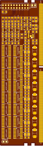
I am in the process of finalizing and developing this PCB. I will build and test each of these boards separately before making the Mother Board.
Just need to supply input signal through Amanero Header, 5V power, output is an OPT transformer.
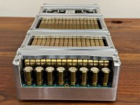
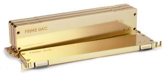
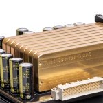
There is a similar implementation of MSB. But I prefer the 2 left and right channels facing each other for shortest and symmetrical input. Each left/right channel will have 8 modules like this attached in parallel (redundancy to be able to attach DDR4-PCM DAC...)
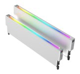
I use DDR4 because its heatsinks are readily available and easy to find.
Just need to supply input signal through Amanero Header, 5V power, output is an OPT transformer.
There is a similar implementation of MSB. But I prefer the 2 left and right channels facing each other for shortest and symmetrical input. Each left/right channel will have 8 modules like this attached in parallel (redundancy to be able to attach DDR4-PCM DAC...)
I use DDR4 because its heatsinks are readily available and easy to find.
Attachments

Last edited:
This is probably not the right thread for your project.I will refresh the 2xDSC base on DDR4 module.

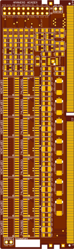
We have made a new version of the PCB. The main change is adding u.fl connectors and adding a JP1 connector, which has some fpga pins.
For example, this connector is compatible with @MarcelvdG firmware 1p2
https://www.diyaudio.com/community/threads/return-to-zero-shift-register-firdac.379406/post-7826909


schematic JP1:

u.fl connectors:
J1 - data
J2 - bclk
J3 - lrck
J4 - mclk
J5 - dataout1
J6 - dsdclock
J7 - dataout2
For example, this connector is compatible with @MarcelvdG firmware 1p2
https://www.diyaudio.com/community/threads/return-to-zero-shift-register-firdac.379406/post-7826909
schematic JP1:
u.fl connectors:
J1 - data
J2 - bclk
J3 - lrck
J4 - mclk
J5 - dataout1
J6 - dsdclock
J7 - dataout2
Attachments
I'm not familiar with the international shipping process. Plus my full-time job is so busy, I can't find time to pack and prepare. I just wanted to show off a little bit of my own DIY project - it motivated me to finish it.Does anyone have a PCB for sale, or a completely finished, tested one?
Hello,
I have a DSD2PCM board implemented in a diferent environtment, no amanero neither DSC.
Need help, not being able to play sound troaught, got just noise, a kind of frequency.
Please see picture, as input use an Spdif receiver, connected all I2s pins:
(Data, Bclk, Fsclk, Mclk, DSD, mute and grounds).
As DAC output, instead of DSC, I use NoDac 4rth order filter, plus an stepup 8x.
I took from de PCM2DSD module output pin 9 (LRCKout) and pin 5 (DATAout) as right and left channel respectively.
Attachments

Which version of firmware did you install?
Do you have a scope?
The MCLK frequency can only be 22/24MHz audio clock frequencies (same as Amanero).
The inversion of DSD_ON must be the same as for an Amanero USB board.
Input sample rates cannot be higher than 24/192 PCM.
Do you have a scope?
The MCLK frequency can only be 22/24MHz audio clock frequencies (same as Amanero).
The inversion of DSD_ON must be the same as for an Amanero USB board.
Input sample rates cannot be higher than 24/192 PCM.
Hi,
This module come to me populated with 1rst firmware install most likely.
Yes I have scoope. Not much confident with it but some basic yes.
DSD_ON pin I just picked from the guessed place, but not labeled neither specs. The entire row seems compatible altrough.
Input sample rate is not exceed 24bit. Sound come from an android TV box. (Better sound quality than TV spdif output)
And MCLK no idea, but as well, not using high definition audio, I guess low clock frequencies.
In some USB boards when DSD is playing from the USB board, DSD_ON will be logic high. For other USB boards DSD_ON will be logic low. Your spdif board must match the Amanero specification.
Here is the Amanero pinout specification you need to use:

You also may need to measure MCLK frequency with your scope.
If it is not around 22MHz or 24MHz, then the DSD converter will not work properly.
Here is the Amanero pinout specification you need to use:
You also may need to measure MCLK frequency with your scope.
If it is not around 22MHz or 24MHz, then the DSD converter will not work properly.
That looks like you either have no master clock or the probe tip or ground makes no contact. It certainly doesn't look like a twentysomething megahertz square wave.
You have to learn how to use the scope and the probes. Especially how to ground the probes.
Right now the scope is set to FFT mode. You don't want that. You just need to see channel 1, with the probe on MCLK, and the probe properly grounded.
Does the scope have an "AUTO" button? What model of scope do you have? The screenshots look kind of like an OWON scope?
Have you checked the scope probe calibration using the scope's built-in calibrator signal?
Also, you need to read the part about grounding starting at around page 40:
https://download.tek.com/document/02_ABCs-of-Probes-Primer.pdf
Then study about using scopes too:
https://download.tek.com/document/03W_8605_7_HR_Letter.pdf
Last edited:
- Home
- Source & Line
- Digital Line Level
- Simple DSD modulator for DSC2