I estimate the output impedance (it's open loop) to be <2 Ohms. It can be run with or without build-out resistors into large capacitive loads. 30 Ohm loads can be driven to the 100 mW range with decent performance.
I've run it on supplies as high as +/-18V or as low as +/-9V. Things head south around +/- 6V. I also included a soft clipping circuit which tracks the rail voltage.
As expected for class-A, the current drain is huge. I use 85 mA Iq/channel typically so the totals run about 200-225 mA.
Do you think it can work for 2W 500mA into 30 Ohm with little adaptation?
Do you think it can work for 2W 500mA into 30 Ohm with little adaptation?
It would require much larger output devices and heatsink along with some additional current gain to produce that level of output (500 mA) with the same linearity.
The principle of "mirroring" the Vbe multiplier and driving the outputs in common mode (offset by Vbe and -Vbe) could be used for higher currents, but this board could only be used as a pre-driver.
Gary Galo's article shows a DC servo for the 1200 that might be a nice add on to your circuit to eliminate any offset.
Thanks for the post.
I've used a similar technique using a simple integrator to offset null a THAT1240, 1243 or 1246.
Having said that the typical output offset I'm seeing around 0-5 mV isn't really a problem but anyone wanting to add it to the circuit could certainly do so by driving the input line receiver's ref pin with the servo.
Dual Class-A II Headphone and Line Amplifier
I wanted to post an update to this project after a long absence.
The original design posted here using a THAT1646/DRV134 wound up not only in headphone amps but wound up being used as line amps in mastering and transfer facilities.
After selling out of the original run of boards I added features. I kept the original biasing scheme, added gain, added the option of overall NFB for outputs >>100mW and "0Ω" (40mΩ) Rout, and sprinkled in more jumpers.
The result is this:

Dual Class-A "DCAO2" Headphone and Line Amplifier Schematic

Dual Class-A II, DCAO2, Headphone and Line Amplifier PC Board
More information can be found here: Pro Audio Design Forum • View topic - Dual Class-A II Line and Headphone Output Board Documents and here: Dual Class-A II Line Output and Headphone Amplifier
I wanted to post an update to this project after a long absence.
The original design posted here using a THAT1646/DRV134 wound up not only in headphone amps but wound up being used as line amps in mastering and transfer facilities.
After selling out of the original run of boards I added features. I kept the original biasing scheme, added gain, added the option of overall NFB for outputs >>100mW and "0Ω" (40mΩ) Rout, and sprinkled in more jumpers.
The result is this:

Dual Class-A "DCAO2" Headphone and Line Amplifier Schematic

Dual Class-A II, DCAO2, Headphone and Line Amplifier PC Board
More information can be found here: Pro Audio Design Forum • View topic - Dual Class-A II Line and Headphone Output Board Documents and here: Dual Class-A II Line Output and Headphone Amplifier
Hi Wayne,
I just built your amp, unbeknownst to me, it was the one from this thread. Prasi did a nice layout and I made it pretty simple without hardly any extra rail smoothing caps.
I posted your schematic in another thread, and Prasi was kind enough to do the layout:
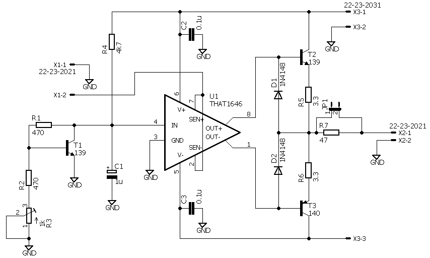
Here is the layout he made:
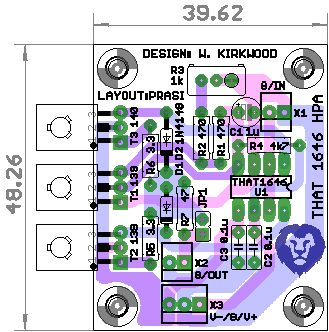
The stereo version is here:
http://www.diyaudio.com/forums/solid-state/310732-esp-hpa-5.html#post5218559
There is even a version that looks more integrated to avoid some PCB fab houses that think you are trying to make 2 boards for the price of one:
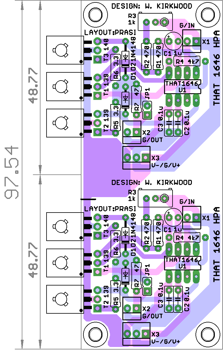
Gerbers here.
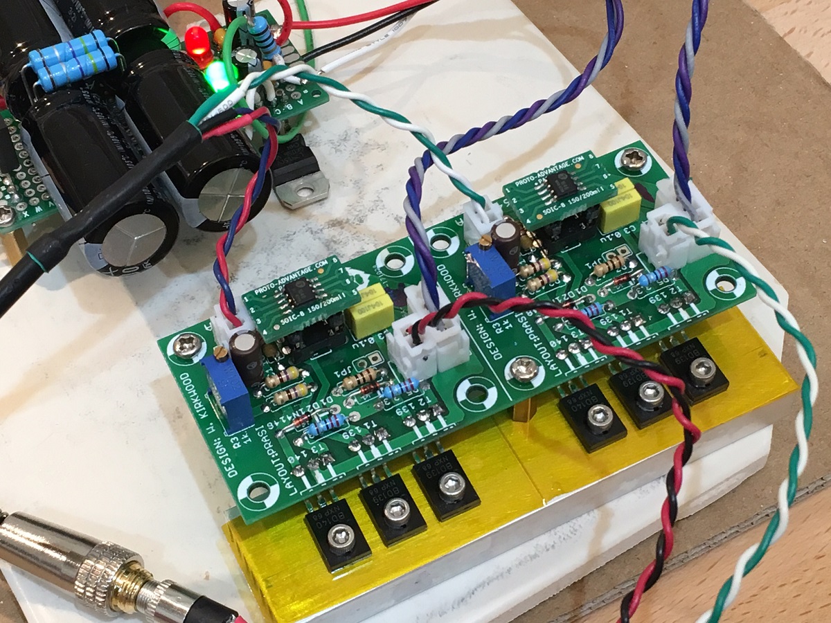
Here is my amp made from PCBs from EasyEDA, using a simple 7815/7915 regulated PSU from a 10w trafo and a 10mF//0.47R//10mF CRC. i am running about 100mA bias current and uisng 2R2 emitter resistors:
And here is a quick measurement with a Focusrite 2i4 USB sound interface. Driving 1.00Vrms into 50ohms. Well, this amp has the distinction of being the lowest distortion amp I have measured. It's below the limits of the 2i4 (-130dB). Anyhow, it sounds really nice.
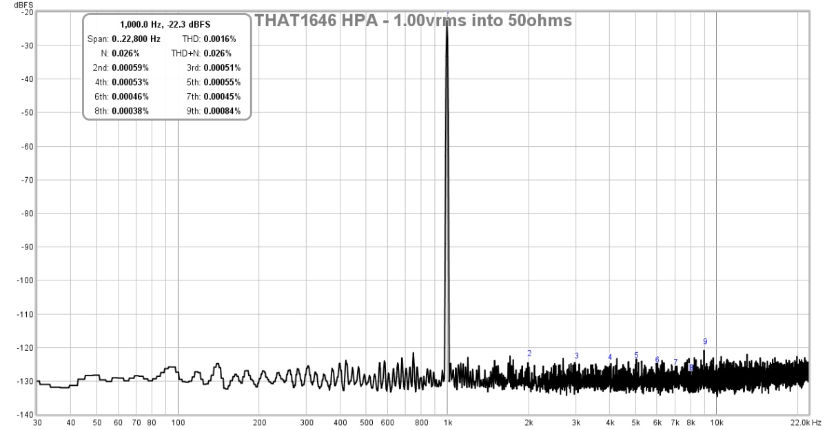
Thanks for a super design. I will probably make a few to use as low distortion instrumentation amps. i will also use one for a low distortion line preamp for my power amp for speakers.
I can highly recommend this amp - very simple to make. A small handfull of cheap parts (under $2) and a $5 THAT1646 driver,
I just built your amp, unbeknownst to me, it was the one from this thread. Prasi did a nice layout and I made it pretty simple without hardly any extra rail smoothing caps.
I posted your schematic in another thread, and Prasi was kind enough to do the layout:
Here is the layout he made:
The stereo version is here:
http://www.diyaudio.com/forums/solid-state/310732-esp-hpa-5.html#post5218559
There is even a version that looks more integrated to avoid some PCB fab houses that think you are trying to make 2 boards for the price of one:
Gerbers here.
Here is my amp made from PCBs from EasyEDA, using a simple 7815/7915 regulated PSU from a 10w trafo and a 10mF//0.47R//10mF CRC. i am running about 100mA bias current and uisng 2R2 emitter resistors:
And here is a quick measurement with a Focusrite 2i4 USB sound interface. Driving 1.00Vrms into 50ohms. Well, this amp has the distinction of being the lowest distortion amp I have measured. It's below the limits of the 2i4 (-130dB). Anyhow, it sounds really nice.
Thanks for a super design. I will probably make a few to use as low distortion instrumentation amps. i will also use one for a low distortion line preamp for my power amp for speakers.
I can highly recommend this amp - very simple to make. A small handfull of cheap parts (under $2) and a $5 THAT1646 driver,
Last edited:
Thank you for the update and the really cool layout. Prasi did a great job. I appreciate the design credit on the layout.
It nice to see interest in this design. I sold out of the original boards a couple of years ago.
The THAT1646 design was also used in the Foote Control Systems mastering compressors to drive the transformer outputs. Up to about 100 mW it provides very low distortion.
For those that needed higher power and sub-Ohm output impedance I replaced it with this one: Dual Class-A II Line Output and Headphone Amplifier
This is the current board minus output transistors:

Though not as simple as the original it's the same topology as the THAT1646 driver (with the THAT1646 replaced by LME49720s) and has either class-A open loop, class-A closed loop and class-A/B closed loop at Pout >100 mW. It's able to produce several watts for difficult-to-drive 'phones.

For those interested in the design you can follow it here: Dual Class-A II Line and Headphone Output Board Documents - Pro Audio Design Forum
If you are really into headphone listening you might consider using my new "elliptic EQ" for bass-to-mono crossfeed. On material that needs it, the low-end "focus" improvement on 'phones is significant. Elliptic Equalizer Boards and Kits
Thanks again for the update. Its great to see interest in this "different" use of the THAT1646.
It nice to see interest in this design. I sold out of the original boards a couple of years ago.
The THAT1646 design was also used in the Foote Control Systems mastering compressors to drive the transformer outputs. Up to about 100 mW it provides very low distortion.
For those that needed higher power and sub-Ohm output impedance I replaced it with this one: Dual Class-A II Line Output and Headphone Amplifier
This is the current board minus output transistors:

Though not as simple as the original it's the same topology as the THAT1646 driver (with the THAT1646 replaced by LME49720s) and has either class-A open loop, class-A closed loop and class-A/B closed loop at Pout >100 mW. It's able to produce several watts for difficult-to-drive 'phones.

For those interested in the design you can follow it here: Dual Class-A II Line and Headphone Output Board Documents - Pro Audio Design Forum
If you are really into headphone listening you might consider using my new "elliptic EQ" for bass-to-mono crossfeed. On material that needs it, the low-end "focus" improvement on 'phones is significant. Elliptic Equalizer Boards and Kits
Thanks again for the update. Its great to see interest in this "different" use of the THAT1646.
Last edited:
Hi~ Guys,
I am newbie here. And I plan to build this THAT1646 headphone amp.
However, I don't know how to trim the R3-the 1K VR.
What can I do for this issues?
I am newbie here. And I plan to build this THAT1646 headphone amp.
However, I don't know how to trim the R3-the 1K VR.
What can I do for this issues?
This is for setting output stage bias current. Adjust depending on heatsinking capabilities and typical load impedance / sensitivity. Bias current can be determined by measuring the voltage across one of the (3R3) emitter resistors and using Ohm's law.
Start with 75 mA or so. 35-50 mA may do for >150 ohm loads, for insensitive 32 ohm loads you might be looking at up to 200 mA.
Start with 75 mA or so. 35-50 mA may do for >150 ohm loads, for insensitive 32 ohm loads you might be looking at up to 200 mA.
This is for setting output stage bias current. Adjust depending on heatsinking capabilities and typical load impedance / sensitivity. Bias current can be determined by measuring the voltage across one of the (3R3) emitter resistors and using Ohm's law.
Start with 75 mA or so. 35-50 mA may do for >150 ohm loads, for insensitive 32 ohm loads you might be looking at up to 200 mA.
Thanks, sgrossklass. I've got it! 😀😀😀
This should be moved to the commercial sector... really.
//
Your reasoning?
In answer to the question:
The 1K trim sets the idle current measured indirectly at the 3R3 emitter resistors. 25-100 mA per channel is about right depending on the load impedance, level and heatsink.
Thanks for the reply from mediatechnology!
one more question, how many gain of the amplifier? Do I need one more Voltage amplifier unit?
Recently, I got a new ATH ATKW headphone. I used the whammy headphone amp and found its 4.75 gain would not fit the headphone. Instead, I refine the gain to 6.25, wow, the amp do great job. Base this experience, I wonder if That 1646 amp had enough gain for the ATH ATKW?
You're welcome!
The voltage gain is unity which was plenty for the Sony 'phones and line amp applications I designed it for.
In your case you might need some additional voltage gain ahead of it - there's no easy way to add it to the existing circuit.
Adding gain was one of the reasons I updated the design around 2015.
An ultralow distortion input stage with something like OPA1656 or LM47920 should work well to get you some gain.
You're welcome. A simple voltage gain stage is really all you need.
Thought it would be a good idea to revisit using a DRV134 instead of a THAT1646.
When using a DRV134 a voltage divider needs to be added to the Vbe multipler.
The THAT1646 has a gain of "2" through it's differential input; the DRV134 a gain of "4." (In Line Driver applications the parts operate similarly.)
Here is the DRV134 schematic that shows the addition of R1 and R2. When using a THAT1646 R1 is not installed and R2 is 0Ω.

Dual Class-A Output schematic using a Current-boosted DRV134
The differential input is used for bias, if the 1646 circuit were not modified for a DRV134 the bias current for the outputs would be excessive.
I ended up using the DRV134 for later builds due to its controlled clipping behavior when using "common mode" drive through the sense pins 2 and 7.
There's a circuit description here for those interested: Dual Class-A Line and Headphone Output Board Documents - Pro Audio Design Forum
For the record I no longer offer boards for the THAT1646/DRV134 so I'm not sure why issue was taken with it being posted here.
Thought it would be a good idea to revisit using a DRV134 instead of a THAT1646.
When using a DRV134 a voltage divider needs to be added to the Vbe multipler.
The THAT1646 has a gain of "2" through it's differential input; the DRV134 a gain of "4." (In Line Driver applications the parts operate similarly.)
Here is the DRV134 schematic that shows the addition of R1 and R2. When using a THAT1646 R1 is not installed and R2 is 0Ω.

Dual Class-A Output schematic using a Current-boosted DRV134
The differential input is used for bias, if the 1646 circuit were not modified for a DRV134 the bias current for the outputs would be excessive.
I ended up using the DRV134 for later builds due to its controlled clipping behavior when using "common mode" drive through the sense pins 2 and 7.
There's a circuit description here for those interested: Dual Class-A Line and Headphone Output Board Documents - Pro Audio Design Forum
For the record I no longer offer boards for the THAT1646/DRV134 so I'm not sure why issue was taken with it being posted here.
Last edited:
Finally, I finished the amp.
One issue emerged. I can't adjust the bias, and the THAT1646 became very hot!
What can be wrong?
Compared to the original schematic, the only difference is that I used a 4.7uF to replaced the 1uF, Is that OK?
One issue emerged. I can't adjust the bias, and the THAT1646 became very hot!
What can be wrong?
Compared to the original schematic, the only difference is that I used a 4.7uF to replaced the 1uF, Is that OK?
Attachments
Last edited:
- Home
- Amplifiers
- Headphone Systems
- Simple Class A Headphone Amp Using THAT1646
