Thanks Wayne! It’s WIP. I’ve been learning TinaTI and wanted to sim your circuit.Nice!
Where is the third transistor/Vbe multiplier? I see the "bias" port on the sch but no circuit.
You don't really need a servo in this circuit. The output Vos is low - it's the sum of the 1646 output offsets plus 1/2 the Vbe difference of the NPN/PNP output pairs. Typically its under 5 mV.
I would remove C2 and C8.
Noted about the servo, thanks! I’ll happily send you a board and source files once completed and tested.
Would it be worth adding
a). small start up delay on the power rails for just the the THAT1686 parts? A voltage ramp start to prevent compression driver damage? I think I can squeeze that from another dual transistor part and a few passives.
b). input level peak meter. Again from another dual transistor part and a few passives and led.
c). do the transistor banks need to permanently loaded with ?mA in any way to prevent shutdown?
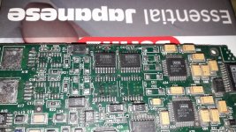
I can't exactly remember what it was, but certainly no soundblaster...It was part of a professional two compound video + sound editing tv station rendering card, basically 2 cards of 30/10 cm size .I will look for the whole thing and tell you if i find it.I think it was something canadian...dreamth:
was that a soundblaster card?
Nice!
Where is the third transistor/Vbe multiplier? It provides thermal feedback. I see the "bias" port on the sch but no circuit.
You don't really need a servo in this circuit. The output Vos is low - it's the sum of the 1646 output offsets plus 1/2 the Vbe difference of the NPN/PNP output pairs. Typically its under 5 mV.
I would remove C2 and C8.
Wayne,
Please find the thread here. 1st draft almost done. Some checking to do after sleep.
https://www.diyaudio.com/community/threads/smd-class-a-headphone-amp-that1646.384945/
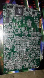
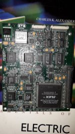
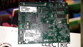
Thanks, I didn't think that it was, based on some of the chips I saw in your picture. I was just curious, so no hurry.I can't exactly remember what it was, but certainly no soundblaster...It was part of a professional two compound video + sound editing tv station rendering card, basically 2 cards of 30/10 cm size .I will look for the whole thing and tell you if i find it.I think it was something canadian...
😉
This was just half of the audio board which had some of the video processing on it too...ad811 , ad 828 op275 op-amps, ssm line drivers snd receivers...top of the line 2001 soundcard.the removed components were just some voltage regulators , two drv134 drivers and some ssm line receivers i used in a headphones amp made in 2012 that i gave later to a friend in 2015.Thanks, I didn't think that it was, based on some of the chips I saw in your picture. I was just curious, so no hurry.
😉
Attachments

The 47 uF across the Vbe multiplier provides start-up delay.
How do you propose to heatsink all those SMT output transistors?
How do you propose to heatsink all those SMT output transistors?
Thanks!The 47 uF across the Vbe multiplier provides start-up delay.
How do you propose to heatsink all those SMT output transistors?
Lots of 0.15mm vias to 4 layers and a pool of potting compound… hopefully
- Home
- Amplifiers
- Headphone Systems
- Simple Class A Headphone Amp Using THAT1646