the diodes in the lower (-ve) half are still upside down.AND the CAPS were a little backwards too!! DUH
Two 50VA transformers are not equivalent to one 100VA transformer.
25Vac is the rated AC voltage when the resistive load draws the full specification output current.
When the transformer is off load it supplies a higher voltage.
A 50VA EI could be ~20% higher voltage.
A 100VA EI could be ~15% higher.
A 100VA toroid could be ~10% higher.
Your 50VA EI will give ~38.5Vdc when mains is at low tolerance and ~45.5Vdc when mains is at maximum tolerance if the transformer regulation is 20%.
A 160VA toroid will give ~34.3Vdc with mains low and ~40.6Vdc when mains is high and transformer regulation is 7%
Note that your 25Vac transformer cannot use 35V smoothing capacitors. It must use 50V capacitors.
Finally, a 160VA transformer can be used to power between 80W of total power and 160W of total power, i.e. 50W+50W of stereo power would be a good target.
Last edited:
Assuming I work out the PS issues.
I revised the schematic on that project removing the bridging and SIM optional components.
Couple of questions
#1 Feedback resistors and caps are they R5,R4 and C3??
These determine overall gain and LF cutoff correct?
#2 How to increase Input Impedance (to about 50K min) and assuming I have no DC from the source and the source is cap coupled to prevent DC back into it can I remove C1? and what is the purpose of C2?
#3 Notes say that C4 determines HF responce this will be a SUB amp so what components determine that POLE so I can lower it?
Any help to a "Bottlehead" would be greatly appreciated!!
C2 blocks high frequencies that are above the audio band.
You can use a buffer at the input, if you like.
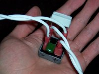
The D1 led is is a clear led that shines a green light when it is on.
There are at least a pair of 220uF missing from the power circuit of that amplifier board schematic.
It goes like +220uF(0v)220uF- (much like a 2-cell flashlight)
Normally those would each be paralleled with 100nF ceramic or polypropylene although a smaller value polyester is workable.
You can also use a 2 uF 250v plastic cap (the same type sold for speaker crossovers) from V+ to V- at the power connections to the amplifier board.
Capacitors located between speaker groundpoint and rectifier are exposed to a lot of voltage and noise, so those caps need to have increased tolerances in order to prevent explosion. 50v to 63v rating will do nicely, but 35v caps may explode or leak. Remember, what returns from the speaker is powerful AC audio.
AndrewT's grounding methods will help your safety, but will also dramatically help the bass of your subwoofer amp.
D1 has another purpose: it is a constant current source for the input differential. I would get rid of it and replace it with two 1N4148 diodes. The reason for this is that you can hardly find two LEDs with the same voltage drop.
D1 has another purpose: it is a constant current source for the input differential. I would get rid of it and replace it with two 1N4148 diodes. The reason for this is that you can hardly find two LEDs with the same voltage drop.
The pair of diodes idea should be seemly in the subwoofer amp project.
Does this require any compensation to the values of other components?
Ok,
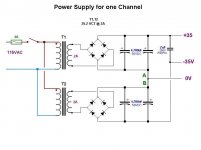
I want to put the PS "to bed". Here I have revised the schematic correcting all the polarity (I think).
Note: This is the supply for ONE channel other channel with be ENTIRELY separate built as two MONO blocks essentially. ie; two more trannies etc.
I realize that the supply voltage will vary +/- maybe 4 volts?
Only questions on the PS are the following.
On the schematic I marked two points "A" and "B". Can or Should I place an additional diode at each point biased so as to "isolate" the two "halves" of the supply? ie; reverse bias the + connection and forward bias the - one?
Excuse me if that is a "dumb" question it just seems to me that doing so would supply 2A's of Positive Rail and 2A's of Negative Rail rather than 4 amps across both? Could just be symantics just asking.
The amp schematic calls for 100nf caps at the inputs so those are left out of the power supply schematic.
All caps will be ATLEAST 50V
Grounding?
The "earth" connection of the power plug will be grounded to the chassis. What configuration should I use for the remaining ground points?
The amp schematic has four ground points.
Obviously I want to "star ground" the junction of (C2,R2 & R8) with C3
Should also C+ be "star grounded" with the junction of C-,C7, speaker earth and 0V?
If so then how should those be returned, joined etc?
Any advantage to using a resistor to chassis earth to "raise" ground above the chassis earth?
Attachments
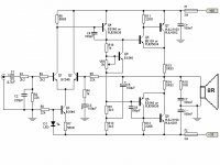
As far as D1 is concerned. It appears that it is used to Bias (about 2V?) and be a CCS of 1.5mA? So the diode idea sounds good. I can use a lighter rocker switch to know if the amp is on. Only question about the 1N4148 is 1.5mA enough to have a good, solid 2V bias?
Monoblocs?
Okay. At the power supply board, there needs to be cable between the 4700uF+4700uF section and the polyester 2uF. . . other way to say the same thing is that, for monoblocs, the 2uF goes onto the amplifier board directly at the attachment point of a short-length cable to the power supply.
At the amplifier board, C+ and C- are shown 100nF. That is insufficient. It needs to be at least 100nF//220uF (parallel 100nF with 220uF) for both C+ and C-.
C+ and C- ground points is the attachment point for the 0v (power supply ground) cable. If these two caps are physically separate, then you can use a 16ga solid core wire to connect their two groundpoints. A "jumper" is the term. Tap the centerpoint measure of that very short bit of solid core wire as the attachment point for the power supply ground cable. For loud dynamics, you can also ground the output RC and the speaker at this point as well.
Last edited:
If you're using the above post as the wiring scheme, you can add a 3.3R resistor to the groundpoint of C3 (ground lift) and cable that via 20ga solid core over to the ground point of R2. Next, cable R2, via 20ga solid core over to the short chunk of 16ga (power star ground) where everything else is grounded.
Over at Decibel Dungeon, there is this photo:
http://myweb.tiscali.co.uk/nuukspot/decdun/gc/groundlift2.jpg
The ground loop breaker needs the thickest cable of all; however, it may be a stranded cable.
One end of the ground loop breaker is for amplifier enclosure and the other end of ground loop breaker is for power star ground. Attach VERY securely. Its for both safety and pretty bass notes.
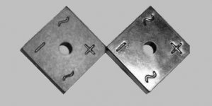
It shows the ground loop breaker schematic, but they just don't make bridge rectifiers that look like that. Here is a photo that illustrates the circuit:
http://myweb.tiscali.co.uk/nuukspot/decdun/gc/groundlift2.jpg
The ground loop breaker needs the thickest cable of all; however, it may be a stranded cable.
One end of the ground loop breaker is for amplifier enclosure and the other end of ground loop breaker is for power star ground. Attach VERY securely. Its for both safety and pretty bass notes.
It shows the ground loop breaker schematic, but they just don't make bridge rectifiers that look like that. Here is a photo that illustrates the circuit:
Attachments
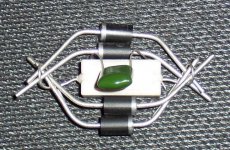
Once I had used cable that was too thick at the small signal ground. . . the power supply ground is thicker yet. . . and by the time I got to the ground loop breaker it was impossible to solder the (thickest) cable without cooking the components. However, the simple solution was to double-up with cable of identical length, like this. . .
The purpose of this device is to ground the metal amplifier enclosure
Edit: An almost identical unit grounds the electronics in my work truck--its chassis was too rusty for reliable connections, and after adding this ground loop breaker, now it starts in a flash each morning and the battery has never run down.
Attachments
Last edited:
As far as D1 is concerned. It appears that it is used to Bias (about 2V?) and be a CCS of 1.5mA? So the diode idea sounds good. I can use a lighter rocker switch to know if the amp is on. Only question about the 1N4148 is 1.5mA enough to have a good, solid 2V bias?
Actually... not really. At that current the voltage drop will be somewhere near 0.65 - 0.7V/diode. Regarding PS, it will work perfectly as you drawn it now, there's no need for other diodes. For groundings and alot of other aspects you should read the articles written by Mr Rod Elliot. You're building his amplifier, afterall.
Thanks all,
After going round and round and upside down, I think my original intent was a "minimalist" design. The "excercise" of looking at different options opened up my mind to the SS stuff versus the tube stuff.
During my research for this possible project I found that "Gainclones" seem to have a "cult" following. This appeals to me in some way, however it appears that most if not all of these implimentations seem to be focused on a much broader frequency range than what I intend to be reproducing.
So what I seem to have "settled on" is the following
PS has been determined, I intend to use "Chipamp.com" PS boards (ala Carlos FM) with the transformers that I have. 25VCT @ 2A. (2) per channel
The chassis will be of similar construction to my Tube amps which is a steel box chassis with wooden base. One chassis with 2 independant "monobloc" amps. I have a rather substantial aluminum heatsink from a "junkpile" find that will be "overkill" but aesthetically fits with the layout. The heatsink will be approximately 3" high and run the full width (10") across the back of the chassis.
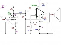
The amplifiers themselves are now the question to be answered. While playing with this I have come up with an idea that might help me in accepting the SS circuitry. What if I were to lower the gain of a gainclone and drive it with a relatively high voltage signal from a tube? Given the very small physical size of the power supplies and amplifiers a 9x13" chassis would leave me enough room to use a medium mu triode as a driver for the amp.
Because the triode gain stage is inverting I would then want to use an inverting gainclone to correct the signal phase. I am hesitant to call this a "hybrid" amp because in essence it's just a "tube preamp" into solid state amps. But for purposes of the overall piece it is a "hybrid". I can place (2) more of the tranformers (I have 8) back to back to give me roughly 120VDC to run the tube.
Any thoughts on this? It really fits with my overall aesthetic and in essence does not add to the complexity since the "overture" circuit can be used AS-IS by coupling the plate output of the tube directly to the input of the chip amp. The low input impedance of the chip amp is OK with the tube since I am not asking it for a lot of gain anyway and a 6CG7 tube would have an output inpedance of about 7K anyway.
Here is a quick sketch of the circuit.
After going round and round and upside down, I think my original intent was a "minimalist" design. The "excercise" of looking at different options opened up my mind to the SS stuff versus the tube stuff.
During my research for this possible project I found that "Gainclones" seem to have a "cult" following. This appeals to me in some way, however it appears that most if not all of these implimentations seem to be focused on a much broader frequency range than what I intend to be reproducing.
So what I seem to have "settled on" is the following
PS has been determined, I intend to use "Chipamp.com" PS boards (ala Carlos FM) with the transformers that I have. 25VCT @ 2A. (2) per channel
The chassis will be of similar construction to my Tube amps which is a steel box chassis with wooden base. One chassis with 2 independant "monobloc" amps. I have a rather substantial aluminum heatsink from a "junkpile" find that will be "overkill" but aesthetically fits with the layout. The heatsink will be approximately 3" high and run the full width (10") across the back of the chassis.
The amplifiers themselves are now the question to be answered. While playing with this I have come up with an idea that might help me in accepting the SS circuitry. What if I were to lower the gain of a gainclone and drive it with a relatively high voltage signal from a tube? Given the very small physical size of the power supplies and amplifiers a 9x13" chassis would leave me enough room to use a medium mu triode as a driver for the amp.
Because the triode gain stage is inverting I would then want to use an inverting gainclone to correct the signal phase. I am hesitant to call this a "hybrid" amp because in essence it's just a "tube preamp" into solid state amps. But for purposes of the overall piece it is a "hybrid". I can place (2) more of the tranformers (I have 8) back to back to give me roughly 120VDC to run the tube.
Any thoughts on this? It really fits with my overall aesthetic and in essence does not add to the complexity since the "overture" circuit can be used AS-IS by coupling the plate output of the tube directly to the input of the chip amp. The low input impedance of the chip amp is OK with the tube since I am not asking it for a lot of gain anyway and a 6CG7 tube would have an output inpedance of about 7K anyway.
Here is a quick sketch of the circuit.
Attachments
The minimum required gain is much different, depending on non-inverting mode or inverting mode, and inverting mode can go much lower. As far as I know, that's generally true of non-unity-stable op amps.
Um, I think that schematic needs an output cap for the subwoofer?
Um, I think that schematic needs an output cap for the subwoofer?
Hi Cold,
what are the values of the feedback resistors?
How did you arrive at the 8uF for the NFB capacitor?
Why no RF filters in front of the buffer/amplifier and again at the front of the power amp?
The 75k between the stages should be connected to Signal ground. Remove it from the common ground tying in Pin7 & pin8.
The 8uF should be connected to Signal ground. Remove it from the common ground.
You have omitted the HF decoupling on the power pins.
You have omitted the output Zobel.
You have omitted a high pass filter at the input (=DC blocking capacitor).
Last edited:
input cap at .5uF x minimum gain of 20 x 1.43 = minimum nfb cap size of 15uF to get bass like a jukebox, so double that cap size to 30uF (or larger!) for a decent result. That's a guess, but it should work.
On that schematic, the speaker needs a more significant ground. . . otherwise it is the opposite of a subwoofer amplifier.
On that schematic, the speaker needs a more significant ground. . . otherwise it is the opposite of a subwoofer amplifier.
OH! yes. Well, with the chipamp.com power supply it has four leads for power.
The V- and pg- of the power supply cable directly to the 100uF cap that you have pictured on the V- rail.
Likewise, the V+ and pg+ of the power supply cable directly to the 100uF cap that you have pictured on the V+ rail.
In this case, the common ground is directly between the pair of 100uF caps, as pictured in the schematic. The ground loop breaker and the speaker may be attached together at this point (midway, 0v, between the 100uF power caps at the amplifier board).
After hookup is complete, the speaker will have been grounded.
Last edited:
I think you need a resistor. Approximately 3.3 ohms will do it. One end attaches to common ground. The other end of the resistor is the new signal ground.
That way you can attach the signal ground components to a signal ground per AndrewT's specs at post 76
That way you can attach the signal ground components to a signal ground per AndrewT's specs at post 76
- Status
- Not open for further replies.
- Home
- Amplifiers
- Chip Amps
- Simple Chip Amp for P to P wiring