This is the worst thread I have ever seen in my life.
/signed
There's NO valuable information despite that some obscure kit is available somewhere.
I will take sakis idea and design a 1GW class D cable amp supplied by surface solar cells... 🙄
based on 741 please !!!!
Will do my best to find a suitable 741-wire 😀
A couple funny things:
1) the PCB states "150W/4 ohms" but the original Thai language site, even showing the same PCB, specs:
2) they sell the full kit for 100 Baht or the PCB alone for 25 Baht
But Currency Exchange Table (Thai Baht) - X-Rates tells me that 25 Thai Baht means 0.8U$S (yes, 80 US Dollar cents).
Either this is a scam, or a family of 30 lives for 1 month on 5$ US.
Take your pick.
By the way, the full kit , 100 Thai Baht, means US 2 Dollars and 40 cents.
As believable as the rest of this thread 😉
EDIT: for those who want to read the original page in English:
http://translate.google.com/transla...etex-audio.com/index.php?topic=2592.0&act=url
1) the PCB states "150W/4 ohms" but the original Thai language site, even showing the same PCB, specs:
(Thanks Google Translate 😉 )50W RMS at 8 ohms load.
80W RMS at 4 ohm load.
100W RMS at 2 ohm load (the power board + /-35V).
2) they sell the full kit for 100 Baht or the PCB alone for 25 Baht
But Currency Exchange Table (Thai Baht) - X-Rates tells me that 25 Thai Baht means 0.8U$S (yes, 80 US Dollar cents).
Either this is a scam, or a family of 30 lives for 1 month on 5$ US.
Take your pick.
By the way, the full kit , 100 Thai Baht, means US 2 Dollars and 40 cents.
As believable as the rest of this thread 😉
EDIT: for those who want to read the original page in English:
http://translate.google.com/transla...etex-audio.com/index.php?topic=2592.0&act=url
Last edited:
Obviously based on this amplifier 2N3055 50W Audio Amplifier which is itself based on the Practical Electronics Texan amplifier developed by Richard Mann of Texas Instruments which can be seen here A Paul Kemble web page - PW Texan amplifier and the PE Rondo. .
Not necessarily. There is still one other way to do it. That one is based on the 'Tiger' output stage which had a reputation for blowing up!
If you trace the PCB the circuit layout is near identical to the first of my references apart from the transistor types, a number of resistor value changes and the bias pot which has been replaced by a fixed 330 resistor.
Please furnish schematics and pcb layout at post 48. what are the parameters of this amplifier. Since it uses LM741, is it really falls under HIFI group.
I still remember the POWER AMP was introduced by Ir. Chandra Ghozali in AUVI Magazine (Audi Video) 1987 specifications 35W at 8 Ohm, then produced by craftsmen many PCB and circulated in the market, following his scheme. 😀
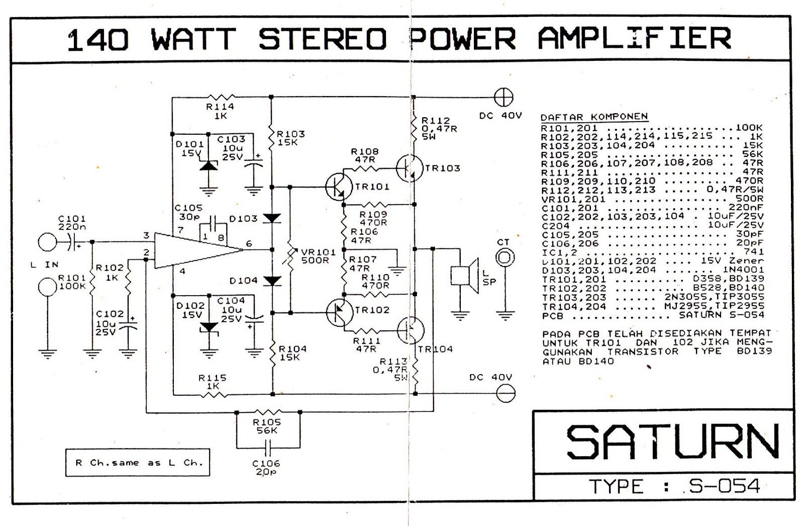
Something is wrong with that circuit. Are you certain that this amp output stage is suppose to be common collector rather than common emitter? IOW, the output stage is wrong and there are some parts missing. 
Plus if class AB bias is intended, than a Vbe multiplier for the drivers is needed.
Plus if class AB bias is intended, than a Vbe multiplier for the drivers is needed.
Last edited:
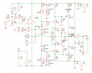
Yes, you are right Mr. CBS240, I attach another scheme
http://2.bp.blogspot.com/-TNWLxIKI0...AAB0/WMli2UTzsZc/s1600/skema+OCL+140+watt.JPG
http://2.bp.blogspot.com/-TNWLxIKI0...AAB0/WMli2UTzsZc/s1600/skema+OCL+140+watt.JPG
Still easy to find this kit here in local shop...
But if we use no more than +/-35VDC, above that rails trouble is a friend 😀
I will tweaked this amp if you can suggest me how to do it, what need to add/changed to the circuit
Regards
But if we use no more than +/-35VDC, above that rails trouble is a friend 😀
I will tweaked this amp if you can suggest me how to do it, what need to add/changed to the circuit
Regards
HI
The diode could be replace by the diamond buffer first two transistor ?
The opamp could Be replace ?
Thanks
The diode could be replace by the diamond buffer first two transistor ?
The opamp could Be replace ?
Thanks
Last edited:
This amp is "stable" up to 40V supply. It has been in Indonesian market for so long. But speaker protector is recommended for this kind of circuit. The subjectively/relatively "good" sound of the circuit is I believe due to CFP output, so if you are after much better sound quality, build Rod Elliot's P3A instead, which uses also CFP output.
A darlington version you can find in this site designed by OnAudio. It is called OPB1. OPB uses CCS instead of simple resistor. OPB uses separate 15V supply for opamp instead of the simple zener supply. OPB uses faster opamp (OPA604). A resistor to supply rail from output transistor's base is found in many similar circuits to limit output bias.
Well, may be I should attach OnAudio's circuit here for quick reference.
Attachments
https://sites.google.com/site/franc...ur/6-9-schemas#TOC-6.9.6-Les-sch-mas-avec-AOP
OPAMP based amplifier schematic
OPAMP based amplifier schematic
But these opamp based ampees do some voltage amplification in the output stage. I believe that is not so good as far as stability is concerned. there are tons of other good (stable) topologies available.pictures dont LIE hottest selling kit now
That's the point.there are tons of other good (stable) topologies available.
The first one is *impossible* , just like that.
The second may work, but:
1) with +/-32V rails, 140W in your dreams only 😉
2) it still is not thermally compensated.
It is recommended to run it underbiased (with some crossover distortion) rather than risk destruction
3) it does not have short protection.
May be acceptable in a home installation, forget it for Pro work (DJ/PA/Musical Instruments)
Anyway the point is: there are better options.
For some reasons I'm still interested with this topology, especially with quasi and darlington output. They can be made out of wastes 😉
140W is for stereo. Well, you know how they treat numbers.
BTW, for no more than 20W you can make a simple and good sounding amp with opamp to beat most (even all) chip amps.
140W is for stereo. Well, you know how they treat numbers.
BTW, for no more than 20W you can make a simple and good sounding amp with opamp to beat most (even all) chip amps.
- Status
- Not open for further replies.
- Home
- Amplifiers
- Solid State
- SIMPLE AMP