I am thinking about building yet another active crossover. I am debating as to either make steeper slope with feedback or just simple lower slope crossover.
Crossover will be ~150Hz as this is what I was always using so far to power mid/tweeters with classA amp and below that with classAB for woofers. Normal stuff.
I am looking for highest purity of tone, highest clarity for mid and tweeter, so less caps the better, plus I am using open baffle with natural roll off. So 6dB/oct should be plenty.
For woofers, I prefer steeper crossover. Can I just combine both types? Will there be negative consequences for phase or uneven fr response around crossover? Or should I stick to the same slope?
Btw, if you see any obvious mistakes on the schematics, please let me know, I just drew it from other active crossovers I have seen around. Thanks.
Attachments
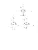
observe hand drawn 18db solution
I can't remember from where I collected that, but it was handy to include on papers
I did made, eons ago, tube based xover that way and it worked nicely
I can't remember from where I collected that, but it was handy to include on papers
I did made, eons ago, tube based xover that way and it worked nicely
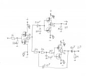
I´m gonna try something similar with diamond buffers and sallen-key-filters whilst hopefully avoiding caps in each and every stage.
First buffer on breadboard was near 0mV. I guess I could end up matching parts nevertheless but that´s OK.
Discrete crossover, sanity check
First buffer on breadboard was near 0mV. I guess I could end up matching parts nevertheless but that´s OK.
Discrete crossover, sanity check
There is a handy calculator at the bottom of the page you can download.
Linkwitz-Riley Electronic Crossover
Linkwitz-Riley Electronic Crossover
I entered equations to the excel and got this
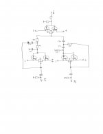
if mixing slopes is no problem, this is what i am going to build
can't get any simpler
one cap upper path
output cap in lower path can be avoided, but its less critical, i may use bipolar
lets built it then
if mixing slopes is no problem, this is what i am going to build
can't get any simpler
one cap upper path
output cap in lower path can be avoided, but its less critical, i may use bipolar
lets built it then
Attachments
With regards to calculators:
There is very good information on the famous Linkwitz site:
Active Filters
The spreadsheets are really good and include most filters one might eventually need.
Finally it´s always good to proof the filters in LTspice or similar.
There is very good information on the famous Linkwitz site:
Active Filters
The spreadsheets are really good and include most filters one might eventually need.
Finally it´s always good to proof the filters in LTspice or similar.

I'm not an expert in x-overs, but this looks good and I appreciate using discrete technique instead of opamps!
I´m aware of that crossover but although its a very cool project, it doesn´t fit my needs so well. There is no such thing as a generic crossover that fits all!
Literally no crossover is a textbook crossover unless you buy textbook-drivers.
And despite, it´s only HP/LP, uses expensive fets. I have open baffle loudspeakers. I need low shelf, dipole equalization and eventually delay and notches.
And how boring is it to not re-invent and to rethink things?
It´s OK if you prefer buying your PCBs and just stupidly solder everything together what somebody else came up with but don´t blame others for doing it differently.
if mixing slopes is no problem, this is what i am going to build
Sometimes mixing slopes is the only way to ensure you get good phase matching 🙂
in response to why reinvent the wheel? Why not! If it helps you learn something and you get enjoyment from it, then what better reason could there be.
We would never get anything new if everyone just built things that had already been done before 🙂
Tony.
I never buy pcbs or kits, I always try to adapt to my needs liking and simplify to the max
I mentioned the pass crossover only as a starting point
for the open baffle you need a T-bass (search it on this site) compensation crossover, it adds bass to open baffle better than EQ
I mentioned the pass crossover only as a starting point
for the open baffle you need a T-bass (search it on this site) compensation crossover, it adds bass to open baffle better than EQ

if mixing slopes is no problem,
I have seen very few crossovers (active or passive) where the slopes and frequencies for any two non-coincident driver combinations is identical. It never works properly if you do that.
VituixCAD allows you to simulate active crossovers by using functional blocks (which you would replace with your circuitry).
I noticed that your schematic does not have any sort of shelving for the baffle step correction, which will be mandatory. Also there is an acoustic offset to be accounted for because of the difference in acoustic centers, which needs to be factored in.

OK, then I misunderstood your comment which didn´t seem to be all that constructive at first.I never buy pcbs or kits, I always try to adapt to my needs liking and simplify to the max
I mentioned the pass crossover only as a starting point
for the open baffle you need a T-bass (search it on this site) compensation crossover, it adds bass to open baffle better than EQ
And many thanks for the "T-bass" hint. Never even heard of that!
And back to topic please! ;-)
- Home
- Amplifiers
- Pass Labs
- simple active crossover