You may find similar circuits in this power range, but it couldn't be more simple than this. This amp uses bare minimum components which are readily available and are cheap. There are better amplifiers out there but the main thing behind this circuit is its simplicity. No need to adjust Vas, Vbe etc.....
You can even make this circuit on a general PCB. Just solder these components and plug to an audio source and you Speakers and you are ready to roll.
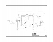
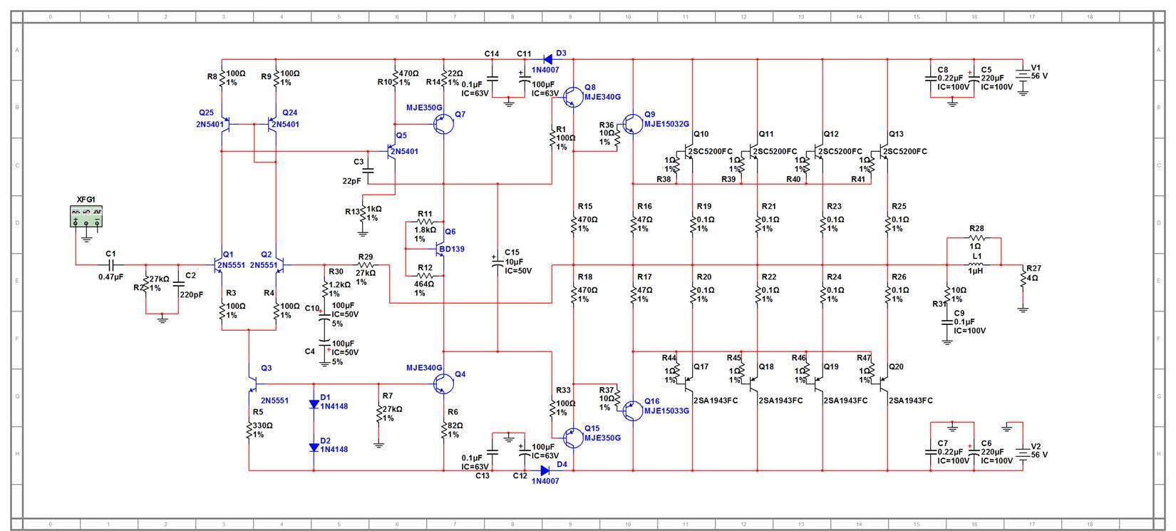
However I made a stereo amplifier and sourced the PCB from a local shop which included a preamp with Volume and tone controls. I am using a 30-0-30 8 ampere transformer with 3, 4700 uF caps for both +ve and -ve rails. I would upload my amplifier pics later and the schematic is attached.
For latest design Goto: http://www.diyaudio.com/forums/solid-state/211635-simple-100w-power-amp-13.html
http://www.diyaudio.com/forums/atta...368301000-simple-100w-power-amp-250w-hifi.jpg
You can even make this circuit on a general PCB. Just solder these components and plug to an audio source and you Speakers and you are ready to roll.
However I made a stereo amplifier and sourced the PCB from a local shop which included a preamp with Volume and tone controls. I am using a 30-0-30 8 ampere transformer with 3, 4700 uF caps for both +ve and -ve rails. I would upload my amplifier pics later and the schematic is attached.
For latest design Goto: http://www.diyaudio.com/forums/solid-state/211635-simple-100w-power-amp-13.html
http://www.diyaudio.com/forums/atta...368301000-simple-100w-power-amp-250w-hifi.jpg
Attachments
Last edited:
It could actually be simplified further, while improving the performance. What I would do:
Replace the 2N3773's with the MJ15003/04 complementary pair, or the better ON Semi pairs like MJL4302/4281. Output stage will now be complementary EF2. I would connect the drivers for class A, removing the lower 100R.
Drop the rails to +/-30 or +/-35Vdc.
Replace the 3k3/Zener with a single 12K or 15K, or jump up to a actual current source. Use better devices for the input pair like KSA992. The NFB cap doesn't need to be a 63V part, 16V or 25V is more than enough.
Replace the VAS device with something better, like a KSA3503, and recalculate/simulate the compensation.
I would also fit a bias trimpot and add the third resistor for safety. You should also have two reverse biased diodes from the output to the rails.
thanx for the replies friends. Its really hard to find genuine MJ15003/4 trans. and the MJL4281/4302 are almost impossible to get. I live in India and these devices are most likely to be fake if bought from a local dealer. The parts used are easily available and are cheap.
sure we could use better trans. but it works and works good.
i used both BD139/140 and TIP122/127 as drivers and both work fine, so any of the pairs could be used, however i would recommend the TIP pair.
sure we could use better trans. but it works and works good.
i used both BD139/140 and TIP122/127 as drivers and both work fine, so any of the pairs could be used, however i would recommend the TIP pair.
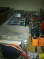
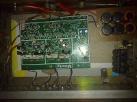
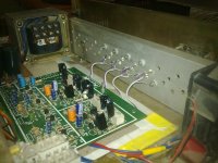
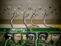
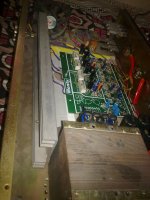
Here are the pics of my build. Please help me to balance the LTP and emitter loads on the two drivers and mention the modifications, changes to be done.
Attachments
Measure the current through the LTP degeneration (emitter) resistors.
They should be identical.
Oh, you don't have any?
Measure the current through the 1k collector resistor and then add the base current going to the VAS Q.
This should give the collector current.
Measure the current through the 3k3 tail resistor.
I3k3 = 2*[I1k0+Ib]
They should be identical.
Oh, you don't have any?
Measure the current through the 1k collector resistor and then add the base current going to the VAS Q.
This should give the collector current.
Measure the current through the 3k3 tail resistor.
I3k3 = 2*[I1k0+Ib]
thanks for the reply,
please help me out more,
what's LTP and what's Vas Q could you describe briefly,
and please advice for any more mods/changes could be done, keeping the circuit simple, to make it better
which other driver trans. could be used using same output trans.
please help me out more,
what's LTP and what's Vas Q could you describe briefly,
and please advice for any more mods/changes could be done, keeping the circuit simple, to make it better
which other driver trans. could be used using same output trans.
very very important : the cable you use from pcb to transistors you need to split it having a flat cable including B C E connections is a very bad thing to do...twisting is even worst .
You need to at least remove the base cable from the pack
You need to at least remove the base cable from the pack
Thanks friends.
I did some changes. Increased the +ve FB resistor to 3.3K from 2.2K.
Increased 3.3K resistor to 5.6K keeping the zener in place. The amp stays cool at idle, but the output trans. get a bit hot while playing music. Sound is really good with crisp treble and clear vocals. Bass is good too.
@Stormrider- KSA3503 are really hard to find, i looked out for MJ15003/4 but they turned out to be fake ON semi's.
@AndrewT- Input trans. are BC556B, please advice if BD139/40 are not good Vas devices. Mention any substitutes.
Regards,
Aniket
Look up Greg's data for devices. He has a table of suggested VAS devices with a few oddballs thrown in for comparison.
Add a second pair of output transistors before attemting >50 watts output into 4 ohms. "
A Crown D150 only uses one pair and can drive 140W/4Ω, the D150AII was rated at 155W/4Ω.
http://www.crownaudio.com/pdf/legacy/D150-spec-sheet.pdf
The original DC300 would do 340W/4Ω at clip with two pair of 2N3773.
A Crown D150 only uses one pair and can drive 140W/4Ω, the D150AII was rated at 155W/4Ω.
http://www.crownaudio.com/pdf/legacy/D150-spec-sheet.pdf
The original DC300 would do 340W/4Ω at clip with two pair of 2N3773.
What is the rail voltages of that crown amp ? Looking at the 2N3773 datasheet, at 50V Vce, you can pull about 3A through a single 2N3773, so up to 50V rails seem to be safe with a 4 ohm load.
"What is the rail voltages of that crown amp ?"
If I remember correctly, about ±50V.
"Should i add more output trans. ??
will this increase performance/ power?? by how much? "
If you like.
If you have a good heatsink and adequate thermal grease and good insulators it is probably OK with one pair.
A second pair would just allow it to handle low impedance loads better, it would probably not put out any more power.
Hello Aniket
A suitable vas transistor sould have a minimum ft of 125 mhz and a cob lower than 10 pf.
Your cdom capacitor of 220 pf are quite much too high value, you should reduce it to 47 pf and also put a 10 pf capacitor between vas collector pin and the base of the second input transistor like in the image I include, this 10 pf capacitor are a phase lead capacitor.
Bye
Gaetan
Attachments

Last edited:
- Status
- Not open for further replies.
- Home
- Amplifiers
- Solid State
- Simple 100W power amp