My HP DMM can read a uA and I could still vary resistance on the LDRs with less than 1uA. I know that because I measured 1uA then applied more resistance in series with 5VDC by turning up the resistance on my pot the resistance on the LDR increased. So why are they so dang sensitive I dont know, but it works for me 🙂
Uriah
Uriah
it's not the LDRs that would be overloaded when using a 500k pot.
I'm wondering whether overloading the 500k pot will affect it's longer term performance, maybe generating a noisy signal from the wiper or just giving up completely.
The power rating for a 3leg potentiometer is determined by the maximum current that the pot track can take.
If you have a 500mW 500k potentiometer, then the maximum rated current is 1mA.
0.001^2 * 5*10^5 = 0.5W.
I would normally select the maximum operating current for half the rated power i.e. <=0.7mA.
A 100k 1W pot can pass more than three times the current but, still well short of the range of currents that the LDRs will demand.
If the pot is set to give less than 5k when feeding a low impedance load from 5V the current exceeds that 1mA rated limit.
This will become a problem at the extremes of the pot rotation.
One pair of diodes will have the high resistance feed and draw tiny currents but the other end of the pot supplies a high current to the other pair of diodes. something approaching 20mA.
I now begin to wonder if this could explain why that DIYer found that constant current mode sounded better. The pot effect was being isolated from the direct current fed to the LDRs.
Andrew,
Thanks for the post. I read the article about potentiometers on Rod Elliots site and with regard to power rating of pots it seems you are right, yet I have been using a .5W DUAL pot for my lightspeed for months with no errors (that I can hear anyway).
I wonder if its different because of the way we are using the pots. We dont use them as pots at all in the lightspeed. They dont connect to ground and are used actually as two separate resistors. I know when they give the rating for the pot they are assuming we are using it as a pot, but suppose I was using a half watt 500k resistor. Would that forumula be the same if I was not using it as a pot but actually as two different resistors?
Most of the time a pot acts as a voltage divider and in this case, it doesnt. In this case it is simply limiting current. Also, we have to consider that there is a voltage drop across the LED of 1.5-2V so we are dealing with a lower voltage than that of the power supply as well. So in your equation we need to consider the LED voltage drop.
Am I right on this? I think I am. Let me know what you think.
Uriah
Uriah,
My latest sets of LDR's arrived this morning - thanks.
I am now running my previous LSA directly into a Pass B1 buffer - it seems to work much better with my PD Patek style gainclone.
However I am torn now between the standard B1 and the DC coupled B1 with shunt psu being developed in another GB thread.
Choices, choices.
Almost forgot to say thanks for the pots.
Alan
Hi Alan,
Good to hear from you again. You are very welcome on the pots. I hope they work out well for everyone.
I am working on a board to adapt to a BrianGT gainclone board. It will replace all resistors on the BrianGT board with LDRs and then provide control over them so you can dial in a 22k feedback resistor, etc. and even tweak it WHILE the amp plays so you can hear the difference.
Also all inputs will be selectable with no switches in the line and no relays either. Hmmm!?!
And an LDR pot will be on board along with 5VDC regulated supply.
Fun Stuff!
Uriah
Does anyone have plans do develop a PCB for a balanced implementation? I think I am going to try it out on proto board but just wanted to put some feelers out there! Maybe this will force me to learn how to design a PCB...
(I think i have too may projects going on at once it my head at this point... DAC's, PC's, Amp's, this little project... )
(I think i have too may projects going on at once it my head at this point... DAC's, PC's, Amp's, this little project... )
Hi Uriah and all.
Is the scheme shown in this post http://www.diyaudio.com/forums/showthread.php?postid=1264140#post1264140 the one to use whith the 500K pot ?
Thanks for your efforts, got my package this morning ! 😉
Is the scheme shown in this post http://www.diyaudio.com/forums/showthread.php?postid=1264140#post1264140 the one to use whith the 500K pot ?
Thanks for your efforts, got my package this morning ! 😉
Hi Korben
Yes. Although you may want to NOT attach your Lightspeed to chassis ground. Doesnt make sense to me to plug two resistors to another ground when you can tie signal gnd to earth gnd in your amp. Up to you. I just think it gives an extra opportunity to introduce noise.
Uriah
Yes. Although you may want to NOT attach your Lightspeed to chassis ground. Doesnt make sense to me to plug two resistors to another ground when you can tie signal gnd to earth gnd in your amp. Up to you. I just think it gives an extra opportunity to introduce noise.
Uriah
Balanced will be dead easy.HaLo6 said:Does anyone have plans do develop a PCB for a balanced implementation?
just one LDR per channel, between hot and cold. Match this pair for channel balance and you are done.
🙂
Glad these are making their way 'round the world.
3 days after I shipped a guy in New Zealand let me know he had his. They dont even make it to Michigan from here that fast!
Uriah
Glad these are making their way 'round the world.
3 days after I shipped a guy in New Zealand let me know he had his. They dont even make it to Michigan from here that fast!
Uriah

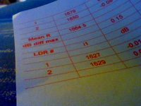
1 and 2 have no significance.
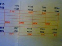
Consider this: your normal listening level is probably between 10% and 60% rotation on the pot.
So anyway the series resistor would then be used most at about 450k-200k.
The series would be used from 50k to 300k.
Make sure that the LDRs you use for series have their best measurements on 200, 300, 400k.
Make sure your shunt resistors have their best measurements from 100, 200, 300k.
So if you have awesome 100, 200, 300k and then all of a sudden something like -.52dB on 400k then this is definitely a great option for shunt and the opposite for series.
Uriah
- Status
- Not open for further replies.
- Home
- Group Buys
- Silonex LDRs for Lightspeed Attenuator