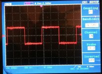
ok.. that make sense... but... why at 15khz i am loosing yhe squareness and it began a sinus like wave ?
ok.. that make sense... but... why at 15khz i am loosing yhe squareness and it began a sinus like wave ?
Try to measure without transformer at all. Only outputs from the device. And without any C or other passive filter elements. Just put some termination resistor from series 22-100Kohm. From parallel R netwotk output to ground. Should be squared shape...
Try to measure without transformer at all. Only outputs from the device. And without any C or other passive filter elements. Just put some termination resistor from series 22-100Kohm. From parallel R netwotk output to ground. Should be squared shape...
i must desolder the transformer to test that... i will for sure..
but i must wait for a spare component for the desoldering gun that has unfortunately broken 😀
i must desolder the transformer to test that... i will for sure..
but i must wait for a spare component for the desoldering gun that has unfortunately broken 😀
OK waiting for the results
.
I put transformers on the female pin holders. Standard. So they are removable.
.
Someone measure output resistance of the device with few frequencies maybe? (And without hfrm-s).
Just to see what is the "generator" internal resistance value. I think based on that should choose coupling xfrm?
i ... think i am an idiot.
i've said that i am using "files" to test generated square waves...
the problem here... is not the DSC, when i was getting "sine-like" 20k square wave... is just me not exporting the test file with proper resolution.
i was using 44.1k, that implies a very limited bandwitdth for the signal...
tested with 192k/384k and now the things look better...
not perfect due to the limitation of this method itself. I think is impossible to get a proper square response with any kind of bandwidth limited support.
hope that make sense.
So... "trap for young players" here...
Do You have maybe some photo?
BTW
I measure pure 20KHz square only with TDA1540 "mother" DAC. Up to 384KHz (not on the CD player but hand made dac... I am not sure maybe it vas also with 1bit "special" DSD circuit with tri-stae ballanced output?)
is a matter of sampling frequency... an fs of 44.1 simply doesnt have the capabilities to carries all the harmonics that a quasre signal carries... and hence the distortion of the square into a sinusoidal-like output.
higher fs.. higher harmonic contents... more "squareness"
higher fs.. higher harmonic contents... more "squareness"
you are certainly right,is a matter of sampling frequency... an fs of 44.1 simply doesnt have the capabilities to carries all the harmonics that a quasre signal carries... and hence the distortion of the square into a sinusoidal-like output.
higher fs.. higher harmonic contents... more "squareness"
i think it can be easily deduced why with a frequency band of only 22 kHz (that's half of 44.1 kHz) a very bad square signal of 15 kHz is obtained. For example, YT shows that the 500 Hz square signal is not very great either. But luckily it's not exactly a signal of music 🙂
YouTube
I found some (not so good) pic from the scope of 20KHz, square. TDA1540 was in NOS mode without digital filter just for the test. Without interstage transformer, just simple output test circuit, Riv + JFET gain stage + JFET buffer... (I didnt believe it at the first look, also findout that it get out with 384KHz SR in NOS mode, but latter note in datasheet 12Mbit datarate. Also note extremly fast changing SRates, without almost any transition or clicks. Much faster than other DACs with SAME USB/I2S interface, and same computer before)
Attachments
Last edited:
My DSC2 measurements
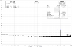
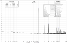
I took some time to make measurements of my DSC2 build (shown at https://www.diyaudio.com/forums/digital-line-level/254935-signalyst-dsc1-141.html#post5830294) before starting case construction. My results do not seem to be in-line with the measurements others are seeing. I'm wondering where I may have gone wrong and if there are any suggestions to get my THD measurements up to par with what other are seeing (https://www.diyaudio.com/forums/digital-line-level/254935-signalyst-dsc1-151.html#post5890188, etc).
While the measurements others have posted are around 0.007% THD, I am consistently seeing 0.013% in one channel, 0.017% on the other. I have attached my RTA spectrums.
Tests were run using a 1khz sine 384k/24bit wav file generated with SoX, -3db attenuation. This is upsampled to DSD512 or 256 in Roon (no meaningful differences in THD between the rates). Balanced output sends about 1.22V output to my Linear Audio Autoranger (which leaves attenuation to 0db) and then to my ESI Juli@'s balanced inputs.
Any thoughts on the cause of this? I have tried a few things to rule out some thoughts.
- Changed from a switch mode PSU with a cap-mx + regulator to a linear PSU + cap-mx + regulator. No changes in THD.
- Tried both SE and Balanced outputs, no change
- Tried HQPlayer instead of Roon for upsampling, no change
- Added 10k across the secondary of the output transformer (Lundahl LL1684), no change
Some suspicions I have:
- I ordered some 74AHCT595Ds from Taobao in an attempted to get old stock. It seems like they were based on NXP marking, but I wonder now if they are legit parts.
- It was stated by Vit123 that the Lundahls add significant distortion, but even for these transformers, is it expected to be this high?
- Any grounding issues? Right now its pretty isolated from anything, but I suspect this wouldn't be that big of an issue with balanced output. I also would assume any grounding issue wouldn't be spread across the harmonics as I'm seeing.
- Soldering or construction errors? Anywhere to start to check this? I read the previous posts about DC across the transformer primary. I measured and there is no substantial or constant DC voltage while playing music.
- Should I add additional snubbing or load to my output with the LL1684s?
- Perhaps my test setup is flawed.
Or... maybe these measurements are as expected with my build?
Any suggestions on where I can go next to try to lower the THD? Any other tests I should be running? Any other information that would be helpful?
Thanks all for your thoughts and expertise!
Greg
Attachments
Maybe measure another DAC, and see how it compares? Especially if you have (or can borrow) a commercial DAC with a data sheet number for THD.
Was wondering if the ladder resistors (and their tolerance, or maybe variance from each other) could impact THD?
There was a reason that Soekris used resistors with 0.02% or thereabouts in his ladder dac.
Randy
Was wondering if the ladder resistors (and their tolerance, or maybe variance from each other) could impact THD?
There was a reason that Soekris used resistors with 0.02% or thereabouts in his ladder dac.
Randy
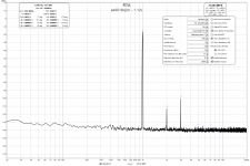
Maybe measure another DAC, and see how it compares? Especially if you have (or can borrow) a commercial DAC with a data sheet number for THD.
I measured a small Roon / raspberry pi-based streamer using an ES9018Q2M with the same test file and setup. It measured 0.0061% THD as shown in the attached file. Therefore, I know at least my test setup can measure lower than what I'm seeing with the DSC2.
Greg
Attachments
Was wondering if the ladder resistors (and their tolerance, or maybe variance from each other) could impact THD?
There was a reason that Soekris used resistors with 0.02% or thereabouts in his ladder dac.
Randy
As far as I know, the Soekris designs are multibit DACs while the Signalyst designs are single-bit FIRDACs. In a multibit design, resistor matching affects distortion a lot, in single-bit FIRDACs, it only affects stopband rejection (suppression of far-ultrasonic rubbish).
@gtose ... Hi ... Just a couple of brief comments on your measurements:
- A suggestion could be to disconnect the Lundahl and measure the DSC directly without transformers.
- Also, I notice that you describe a measurement setup that includes the Linear Audio Autoranger. Personally I would try measuring without this part in the signal chain.
- Given there's virtually no noise below 1 kHz I would not assume that you have ground loop issues ...
- Might the input impedance of any of the devices you connect after the DSC have low impedances so as to load the DSC?
Well, these were my first thoughts ... hope it may help ...
Cheers,
Jesper
I may have some, I'll let you know in a few hours with a PM.
Chris
if you got philips... i am interested too...
anyway, whoever needs NXP ... i have them
Hello;
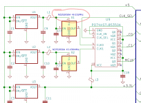
Regarding to version DSC2 with reclocking what i do not understand is dsd is always times of 44.1Khz
DSD 64 : DSD 2.8 MHz = 2 822 400 Hz = 44100 Hz x 64 times;
DSD 128 : DSD 5.6 MHz = 5 644 800 Hz = 44100 Hz x 128 times;
DSD 256 : DSD 11.2 MHz = 11 289 600 Hz = 44100 Hz x 256 times;
DSD 512 : DSD 22.6 MHz = 22 579 200 Hz = 44100 Hz x 512 times;
DSD 1024 : DSD 45.2 MHz = 45 158 400 Hz = 44100 Hz x 1024 times;
So why recloking circuit includes 49.152Mhz?
Attachments
- Home
- Source & Line
- Digital Line Level
- Signalyst DSC1