My DSC1 PCB arrived today, quality seems good on first impressions.
I'll post some pictures later this evening.
It also includes a BOM (for all the SMD parts, the through hole BOM is on the ebay listing) so should be able to finalise my own parts list now.
Ray
I'll post some pictures later this evening.
It also includes a BOM (for all the SMD parts, the through hole BOM is on the ebay listing) so should be able to finalise my own parts list now.
Ray
Good to know that quality is good. I ordered two of them with friend, we expect arriving after 8.08.
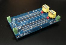
Here are some pictures of the PCB, as you can see, a neat layout with crisp, clean tracks. Registration looks OK. I obviously can't comment on the circuit implementation...
Ray
Ray
An externally hosted image should be here but it was not working when we last tested it.
An externally hosted image should be here but it was not working when we last tested it.
An externally hosted image should be here but it was not working when we last tested it.
An externally hosted image should be here but it was not working when we last tested it.
The smd soldering isn't as bad as I imagined it was going to be, I might even get the hang of it before I finish the board!
An externally hosted image should be here but it was not working when we last tested it.
The smd soldering isn't as bad as I imagined it was going to be, I might even get the hang of it before I finish the board!
😉 .... Jesper
I'm looking for a little assistance with the components for my DSC1 project.
Sheet 4 of the schematic has R806 and R816 annotated at 'NI' and I'm not sure what 'NI' means in this context; could be 'nil-impedance' or 'not inserted' or....
Will be grateful if someone could clarify for me.
Cheers
Ray
Sheet 4 of the schematic has R806 and R816 annotated at 'NI' and I'm not sure what 'NI' means in this context; could be 'nil-impedance' or 'not inserted' or....
Will be grateful if someone could clarify for me.
Cheers
Ray
Sheet 4 of the schematic has R806 and R816 annotated at 'NI' and I'm not sure what 'NI' means in this context; could be 'nil-impedance' or 'not inserted' or....
You can change gain by placing suitable resistor at R806/R816 which are there, but marked "NI" (Not Installed) for that reason.
Maybe it helps, i hope...
Funny thread. Hi there.
I've received the above mentioned chinese board yesterday and assembled today. Came across this topic only after ordering it. Many thanks to the author.
Unlike most of diyaudio topics, this one says really nothing on the SOUND of this design in 27 pages of tech discussions, that's why I call it funny. 🙂
As of now the board's been done in original schematics, except the resistor matrix: I bought 4.99k Susumu 0.1% resistors instead of 15k, which (I believe) is going to somewhat improve SNR. Got a pair of ad844's, a pair of lme49713's, and an idea of composite opamp in the i/v. Will listen soon, and see what's next.
All the voltages will be supplied by Jung's "super regs". The SRC is AK4137. If I see a good potential in this design (now I only feel it) the next step will be an own SRC on a FPGA.
Will look forward to reading about your results.
Slow progress on my own build of the Chinese board due to other commitments but I'll get there...
Have you noticed that the Chinese board doesn't incorporate the grounding updates Jussi published here;
http://www.diyaudio.com/forums/digital-line-level/254935-signalyst-dsc1-2.html#post4104608
It looks like the schematics were not updated for these changes as they predate the above post by several months.
Instead of AGnd and DGnd connecting at pin3 of the AD844s they connect via L15 (Chinese BOM doesn't state type or value).
The schematic (and Chinese PCB) do include a 100K resistor to ground from pin6 of the AD844 but it is on the output side of the 2.2uF capacitor.
It looks as though some modifications are needed to the Chinese PCB (simple enough) to comply with Jussi's updates.
Cheers
Last edited:
I've bought this board as a prototype for deep reworking - so yes, I'll implement those fixes first, thank you. 🙂
I agree that the ferrite bead put by the Chinese router is definitely not in place, there must be a thick solid wire connected to I/V stage.
I agree that the ferrite bead put by the Chinese router is definitely not in place, there must be a thick solid wire connected to I/V stage.
Yes, I will run a wire from the DGnd pad of the ferrite bead to pin 3 of each AD844.
With the 100K resistor, the extra (electrolytic) pads for the 2.2uF cap make it easy to move the resistor connection to the input side, but I guess you've worked that out already.
For gain, I've left R1/2 (499R) and used 7.87K Susumu RG 0.1% resistors in the filter network.
With the 100K resistor, the extra (electrolytic) pads for the 2.2uF cap make it easy to move the resistor connection to the input side, but I guess you've worked that out already.
For gain, I've left R1/2 (499R) and used 7.87K Susumu RG 0.1% resistors in the filter network.
Attachments
Whoa. This chinese guy is just ahead of me. 😀 No i/v stage at all?
The transformers are the I/V stage (and perhaps gain as well)?
Looks like an interesting project and it would be good to get a PCB to try it, maybe with a nice pair of Llundahls on the output.
I wonder if Jussi has any thoughts on it.
Ray
Transformers are I/I and V/V, at least in my universe. 😉
I consider using them as filters - not these tiny toys of course. Let things develop. I see no problem in using the existing pcb for tests.
I consider using them as filters - not these tiny toys of course. Let things develop. I see no problem in using the existing pcb for tests.
It is not possible to see your attached image
- Home
- Source & Line
- Digital Line Level
- Signalyst DSC1