Other possibility is 74LVC8T595.
It can be used with separate power supply for in- and output. So you can use 3.3V for the input VCC(A) and 5.5V for the output VCC(B).
The big advantage, besides level matching, is that you can use a separate and cleaner power supply for the output.
When I played with this DAC topology, I didn't have an 8T595, so I used a regular 595 and a SN74LVC8T245 buffer after.
Alex.

Indeed, a big advantage, that is why it was adopted for DSC3.
Also all links have been updated from the global mouser site including the datasheets.
The transformers have the link where to purchase them.
I can recommend the AT1 transformers, They do a verry good job.
I have not selected on the availability, the items in the ibom ware available when we ordered the items.
As you know that can change, finding an replacement part is your own...
I have the iBOM updated with the parts, whare Mouser parts are available i have used the MN (Mouser partNumber).Oké i will put the bom here with the mouser parts.
Tot update the ibom is not funny in kicad.
Also all links have been updated from the global mouser site including the datasheets.
The transformers have the link where to purchase them.
I can recommend the AT1 transformers, They do a verry good job.
I have not selected on the availability, the items in the ibom ware available when we ordered the items.
As you know that can change, finding an replacement part is your own...
The question I have about the schematic I saw is why are the clocks not on the output side of the dac where the D->A conversion is being done? Sending the the clocks over there through an isolator is mind-boggling to make sense of. Its asking for more than necessary jitter issues.
Another thing is about the assumption that balanced is better than single-ended. I know the theory and why balanced is supposed to be better, but in practice sometimes balanced isn't better. While there may not be theory to explain why right now today, listening may say that something is not quite so perfect with balanced as theory would predict.
Also, non-stellar audio output transformers are IME not such a good solution. SOA transformers, yes, that could be pretty good. Off the shelf units from Aliexpress, not so good IME.
Too many compromises is the way it looks to me, and not enough attention on how to take it to the next higher level.
If the alternative dac is the @MarcelvdG RTZ dac, then at least its possible to arrange the circuitry around it for spectacular results. Not so straightforward to do with this dac.
Last edited:
Yes, isolation and reclocking would be better. I have Reclocking on top with LVC1G79/80. Just send the isolated signal to DDR4 Module.
I use socket module form so I can take advantage of everything. In the future there will also be RTZ FIRDAC implemented on DDR4 Socket like this.
I use socket module form so I can take advantage of everything. In the future there will also be RTZ FIRDAC implemented on DDR4 Socket like this.
Vcc = 3.3V and signal = 3.3V.Be careful:
If Vcc=3.3, and signals are 3.3v - LVC is good, AHCT not recommended.
If Vcc=5v and signals are 5v - both can be used.
If Vcc=5v and signals are 3.3v - AHCT is good, LVC not recommended.
Alex.
I will use the 74LVC595 with +-50mA current output (x2 AHCT - only +-25mA).
To me it is not clear if this is a general remark or feedback on the trafo's used for DSC3 (Joyin T1). The selected DSC3 trafo's have very wide bandwidth, are very clean on the output and have very low distortion. In my experience they are SOA.Audio transformers may benefit from being degaussed when new. For line level transformers, they can be driven with high-ish line level audio, or with something like pink noise, for maybe a couple of days (while loaded nominally, say maybe with 10k resistors).
Also, for dac use its probably better to have transformers with copper tape shields between primary and secondaries. Its harder for the manufacturer to get wide bandwidth that way, since its easier to rely on capacitive coupling between primary and secondary to extend HF bandwidth. However, having a shield connected to the output side ground should help reduce coupling of RF common mode noise from the dac output into the transformer secondaries.
Actually I much prefer the simple filter with capacitor output with a DHT buffer after.
Problem I have right now is pop noise during sample rate change can't be muted.

Problem I have right now is pop noise during sample rate change can't be muted.
I am using DSC 2.6.2 - with OPT transformer output in Single End mode. If I use ground from one output of secondary winding will get shaking sound. If I connect secondary ground to primary ground (which is also DAC ground) then shaking sound will disappear. But that will lose isolation effect and cancel ground loop between DAC GND and Analog GND.
This is why!? If OPT has a copper shield between primary and secondary - I will definitely try this copper shield as ground but Joyin unfortunately does not have it.
This is why!? If OPT has a copper shield between primary and secondary - I will definitely try this copper shield as ground but Joyin unfortunately does not have it.
Is this comment on DSC3 or the clienttechnical design?The question I have about the schematic I saw is why are the clocks not on the output side of the dac where the D->A conversion is being done? Sending the the clocks over there through an isolator is mind-boggling to make sense of. Its asking for more than necessary jitter issues.
Another thing is about the assumption that balanced is better than single-ended. I know the theory and why balanced is supposed to be better, but in practice sometimes balanced isn't better. While there may not be theory to explain why right now today, listening may say that something is not quite so perfect with balanced as theory would predict.
Also, non-stellar audio output transformers are IME not such a good solution. SOA transformers, yes, that could be pretty good. Off the shelf units from Aliexpress, not so good IME.
Too many compromises is the way it looks to me, and not enough attention on how to take it to the next higher level.
If the alternative dac is the @MarcelvdG RTZ dac, then at least its possible to arrange the circuitry around it for spectacular results. Not so straightforward to do with this dac.
For DSC3 the masterclock is as close as possible to the shift registers with a nice symmetrical layout. The isolator is used to send the masterclock from the Crysteks to the USB interface (Amanero or Xing U30) who are working in slave mode. So the isolator has 5 forward channels for mute, clock select and DSD signals and 1 return channel to feed masterclock to USB interface which outputs I2S. This way complete galvanic isolation between USB to I2S interface and DAC is achieved, while at the DAC side the Crystek clock dictates directly the timing of the shift registers.
When I check with measurements, balanced has lower noise floor than unbalanced and has less distortion (K2 becomes less than K3). Noise floor is close to -150dB. In fact it is the noisefloor of my soundcard.
Last edited:
What is this noise!? Is it the noise (pop) when Next/Stop to Play!? If this is the case, I think it can be solved by delay the Mute signal with RC.Actually I much prefer the simple filter with capacitor output with a DHT buffer after.
Problem I have right now is pop noise during sample rate change can't be muted.
View attachment 1388718
No, this will not help and is not the cause of your problem. The cause of your problem is single end mode.I am using DSC 2.6.2 - with OPT transformer output in Single End mode. If I use ground from one output of secondary winding will get shaking sound. If I connect secondary ground to primary ground (which is also DAC ground) then shaking sound will disappear. But that will lose isolation effect and cancel ground loop between DAC GND and Analog GND.
This is why!? If OPT has a copper shield between primary and secondary - I will definitely try this copper shield as ground but Joyin unfortunately does not have it.
If you use XLR connection, just put center tap of the secondary winding to XLR pin1 (GND). Not to GND of the DAC. It will perfectly eliminate any common mode noise.
Thank you. I have ordered a pair to try.To me it is not clear if this is a general remark or feedback on the trafo's used for DSC3 (Joyin T1). The selected DSC3 trafo's have very wide bandwidth, are very clean on the output and have very low distortion. In my experience they are SOA.
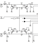
EDIT: Found the schematic.
Transformers do not appear to have an internal primary to secondary electrostatic shield, nor a shielded case.
Looking again, clocks do appear to directly drive the shift registers in this version. However ferrites on the clock power inputs are IME not such a good idea.
Last edited:
It's the pop noise switching tracks when there is rate change 44k<>48K, background noise I think the DHT is louder.What is this noise!? Is it the noise (pop) when Next/Stop to Play!? If this is the case, I think it can be solved by delay the Mute signal with RC.
With hqplayer and BBB/NAA, this mute delay needs to be 2-3 seconds at least.
Will play around with the mute line.
Attachments
Last edited:
A grounded case, that is. For electrostatic shielding....nor a shielded case.
Correction, mute pin is 0 for mute, 1 for music.It's the pop noise switching tracks when there is rate change 44k<>48K, background noise I think the DHT is louder.
With hqplayer and BBB/NAA, this mute delay needs to be 2-3 seconds at least.
Will play around with the mute line.
There are two pops during rate change,
Initial one is so quick even though relay responds right away.
Second one can be muted with delay (3K & 15uf).
I am using the default JP5 (PIN28) and JP6 (mute MR pin on 8T595)
Actually I solved the problem by changing the JP6 setting so MR is always high not depending on mute.
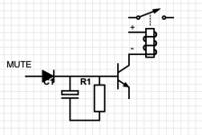
I would never use a mechanical Relay for muting as it always has a large delay and often has a Pop when the contacts hit. Instead I would use an Opto-Transistor at the final output of the Analog. The Opto input can use a Schmitt-Trigger like SN74LVC1G14/17 for buffering. The front of the 1G14/17 can use an R-C (Ceramic) for Delay. Commercial products often use this method.
Attachments
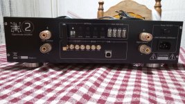
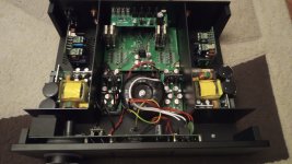
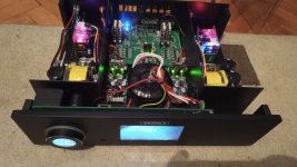
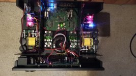
After so much development, problems, finally got sound from the device : ) The relay based tone control is definitely worth it, the treble has become nice and soft, I'm very happy. Next is shielding, I have to shield that analog part with something, in revision 3 everything will go horizontally and the preamp + tone control have to be shielded, I'm very happy, especially that I finally managed to get the device running, I'm also very happy that I removed the Amanero and replaced it with the ct7601, it works very well. Plan for version 3 is: to move torus transformer to the front panel, and make single main pcb, that way is easier for mount and in the same time the less wiring, better. More shileding. Two more section regulators, the free space will be nicely filled to the max.
Attachments
Last edited:
Hi all,
I just finished assembling the DSC 3 board. Transformers are on order (using a LAB DC PSU for now). I must admit I had a few problems to get the DAC to output signals. I have not yet manage to get it working with the Amanero but with the Beablebone works ok for me.
I have bypassed the relays for now. I think that they are the wrong model in the BOM they should be IM03TS non latching instead of the ones in the BOM v2 (IM43TS are listed in the BOM, easy mistake to make when building a BOM that big. These are latching and to unlatch then a negative voltage is required, yes strange). I was seeing a signal on the I/V resistor but I was losing it after the relay so for now I have bypassed the relays but I am seeing that some people are experiencing POPs during rate change so I might put them back (IM03TS).
Also I have taken some notes from the assembly and test process so I will share it just to hopefully help some people as I found the lack of a guide the biggest obstacle to building the DSC). There is not much in terms of original content but merely a collection of forum post information/notes all put together in one place.
The DSC3 sounds very nice but a little different from my reference (Holo May). I have found that the HQplayer settings make a big difference to the overall DAC tonality so it is difficult to compare it with another DAC. Ultimately I will compare the DSC3 to the HOLO May by playing the same DSD upscaled content from HQ player on both DACs to compare Apples with Avocados 🙂
- Home
- Source & Line
- Digital Line Level
- Signalyst DSC1