Have been reading up for days but feel I would need much more electronics knowledge than I do. It seems to be a popular subject ... grounding!
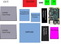
Attached is an amp I am building. I have two transformers and an SMPS supply. I will be source selcting via switch between auxiallry XLR input and an internal raspberry pi hifiberry - unbalanced.
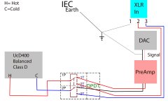
My first question is whether the UcD module needs an earth ground connection to signal ground when using RCA? Or will it just amplify the difference between signal ground and signal?
I ask this because Hypex have instructions on the design of the switch between XLR and unbalanced - have attached my understanding of this switch and it explicitly states to connect RCA signal ground to chassis.
I get more confused when it comes to the regulators for the raspberry pi and pre amp. If I connect the negative output of the Pi regulator board to chassis then I have referenced signal ground of the Pi hifiberry to earth? is this true?
There then seems little point in referencing the hifiberry output gnd to the chassis as this will already be at chassis ground? Is this true?
When the hifiberry signal passes to the preamp (Simple NE5534 buffer) - does it matter if the NE5534 supply is floating? I think it does... So would this mean I need to tie the NE5534 regulator to chassis also?
And then (you can see my confusion) Does the SMPS400 need grounding too? I undertstand that I can float this also as I have spacers bewteen the SMPS and chassis - BUT - apparently the UCD Modules are grounded through the heatsinks?
Which leads me back to my first point - should I be floating the entire unbalanced signal - Pi Hifiberry - Preamp....
Sorry for the mess I've just dumped into the forum but any answers to any of the above will help enormously as my electronics education is not keeping pace with this amp build!
Attached is an amp I am building. I have two transformers and an SMPS supply. I will be source selcting via switch between auxiallry XLR input and an internal raspberry pi hifiberry - unbalanced.
My first question is whether the UcD module needs an earth ground connection to signal ground when using RCA? Or will it just amplify the difference between signal ground and signal?
I ask this because Hypex have instructions on the design of the switch between XLR and unbalanced - have attached my understanding of this switch and it explicitly states to connect RCA signal ground to chassis.
I get more confused when it comes to the regulators for the raspberry pi and pre amp. If I connect the negative output of the Pi regulator board to chassis then I have referenced signal ground of the Pi hifiberry to earth? is this true?
There then seems little point in referencing the hifiberry output gnd to the chassis as this will already be at chassis ground? Is this true?
When the hifiberry signal passes to the preamp (Simple NE5534 buffer) - does it matter if the NE5534 supply is floating? I think it does... So would this mean I need to tie the NE5534 regulator to chassis also?
And then (you can see my confusion) Does the SMPS400 need grounding too? I undertstand that I can float this also as I have spacers bewteen the SMPS and chassis - BUT - apparently the UCD Modules are grounded through the heatsinks?
Which leads me back to my first point - should I be floating the entire unbalanced signal - Pi Hifiberry - Preamp....
Sorry for the mess I've just dumped into the forum but any answers to any of the above will help enormously as my electronics education is not keeping pace with this amp build!
Attachments
There is no need to take all three chassis connections to the same fixing.
There are reasons to deliberately take all three chassis connections via short wires to separate chassis fixings.
There are reasons to deliberately take all three chassis connections via short wires to separate chassis fixings.
Last edited:
The chassis has three purposes and none of them affect the audio operation.
a.) the chassis holds the electronics.
b.) the chassis/enclosure screens the electronics from external interference
c.) the chassis takes fault current via PE to Earth and blows the mains fuse.
Pin1 is a screening part and goes direct to chassis at the connector. It allows the cable screen/shield to become an extension of the enclosure.
For Safety the exposed conductive parts should be connected to the protected chassis. This is not an audio performance requirement. It generally makes audio performance worse. It is a safety requirement.
The chassis should not be used as an Audio ground.
Last edited:
Thanks Andrew, the enclosure is an extension of the shield via pin 1. Got it.
IEC earth will also go to chassis as I am uncomfortable in making the entire amp double insulated.
BUT I am still unsure of my separate internal Pi (DAC and preamp) source signal. This is unbalanced and one transformer powers the Pi (DAC) and another tansformer powers the preamp (Simple ne5534 buffer)
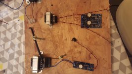
I have attached a pic (probably unnecessary) of the separate supplies for this audio circuit, you can see the two regulator boards, one giving +/- 5V for the Pi and DAC and the other is dual rail running from two separate secondaries as both regulator boards are positive. I intend to tie these two boards in the middle to give me my common gnd.
My question is.... if I tie these supplies to the the chassis after regulation then doesn't this mean that my audio signal is referenced to chassis ground?
If I don't tie them to chassis and leave them floating then does it matter that both the Pi (Dac) and the preamp will be at different potentials?
IEC earth will also go to chassis as I am uncomfortable in making the entire amp double insulated.
BUT I am still unsure of my separate internal Pi (DAC and preamp) source signal. This is unbalanced and one transformer powers the Pi (DAC) and another tansformer powers the preamp (Simple ne5534 buffer)
I have attached a pic (probably unnecessary) of the separate supplies for this audio circuit, you can see the two regulator boards, one giving +/- 5V for the Pi and DAC and the other is dual rail running from two separate secondaries as both regulator boards are positive. I intend to tie these two boards in the middle to give me my common gnd.
My question is.... if I tie these supplies to the the chassis after regulation then doesn't this mean that my audio signal is referenced to chassis ground?
If I don't tie them to chassis and leave them floating then does it matter that both the Pi (Dac) and the preamp will be at different potentials?
Attachments
Thanks Andrew, but that is exactly what I am trying to understand... If power supplies for audio circuits are referenced to ground (Chassis) then surely the audio circuit inherits the chassis ground as its audio ground?
No.
The power supply voltage is referenced to the power supply Zero Volts.
That PSU Zero Volts goes to the client circuit. It does not go to the chassis/enclosure.
Remember that the single connection from PE to your exposed conductive parts is a SAFETY requirement.
This Safety connection has NOTHING to do with circuit operation.
The circuit will work without an enclosure. It only need an enclosure for those three reasons I listed in post3.
a] The Protective Earth/Safety Ground should connect to the chassis near the AC power connector.
b] The interconnect shields should connect to the chassis at their chassis connectors.
c] The DC power supply common (aka ground) should connect to the chassis at a single point.
d] The audio circuit common (aka ground) should connect to the chassis at that same single point.
e] That single point should be near the input interconnect chassis connectors.
the above is correcta] The Protective Earth/Safety Ground should connect to the chassis near the AC power connector.
b] The interconnect shields should connect to the chassis at their chassis connectors.
I don't agree with these latter three.c] The DC power supply common (aka ground) should connect to the chassis at a single point.
d] The audio circuit common (aka ground) should connect to the chassis at that same single point.
e] That single point should be near the input interconnect chassis connectors.
For audio performance the DC power supply common (PSU Zero Volts) does not need to connect to the chassis/enclosure.
The audio circuit common does not need to go to the chassis.
And it follows that the common point between those two does not need to go to the chassis.
The audio circuits should all be interconnected with their two wire, or three wire, (the PSU dual polarity wires), low loop area connectors.
Any voltage references required between any of the audio circuits should go to a voltage reference, dedicated to the audio, not chassis/enclosure.
After all that is done, then make the equipment safer by complying with:
All exposed conductive parts should be connected to the protected chassis. This can be a single wire connection from some current capable point in the audio circuits to chassis. This is NOT an audio connection. This single wire connection and the point it uses for the safety connection must be capable of passing Fault Current that can approach kA and may even exceed that.
Ok, thanks Andrew - so although I have two transformers and separate regulators, I can connect the 0V outputs together and call this a voltage reference 0V. Presumably it will force the two DC circuits to have the same potential for their common 0V
Quote: This can be a single wire connection from some current capable point in the audio circuits to chassis. This is NOT an audio connection. This single wire connection and the point it uses for the safety connection must be capable of passing Fault Current that can approach kA and may even exceed that.
How does the above not become an audio connection? And do you mean from the Raspberry Pi AND preamp board?
And now that I have floated my DC for the audio circuitry, how does this relate to diagram 2 of my original post. Do I just lift the audio common connection that goes from Pi DAC Preamp?
This is from the Hypex website:
Install a DPDT switch to connect the hot/cold inputs of the UcD module to either pins 2/3 of the XLR connector or to the signal and shell contacts of the RCA connector. Note that pin 1 of the XLR connector is not switched, but remains hardwired to chassis. The RCA shell contact also remains hardwired to the chassis. This means that when the DPDT switch is set to RCA, the cold input of the UcD module is grounded via the RCA connector.
Is it not necessary to connect the RCA shell (audio ground / common) to chassis so that the cold input of the UcD module is grounded via the RCA connector?
I don't know why the UcD instructions say that the RCA barrel should be connected to the chassis.
That is different from just about every other Builder/Designer.
That is different from just about every other Builder/Designer.
I would definitely use differential signaling inside the chassis throughout and forget the grounding thing, otherwise the switching power units associated common mode noise could be a horrible problem to deal with.
This is from the Hypex website:
Install a DPDT switch to connect the hot/cold inputs of the UcD module to either pins 2/3 of the XLR connector or to the signal and shell contacts of the RCA connector. Note that pin 1 of the XLR connector is not switched, but remains hardwired to chassis. The RCA shell contact also remains hardwired to the chassis. This means that when the DPDT switch is set to RCA, the cold input of the UcD module is grounded via the RCA connector.
Is it not necessary to connect the RCA shell (audio ground / common) to chassis so that the cold input of the UcD module is grounded via the RCA connector?
Hypex also has this nice application note: http://hypex.nl/component/weblinks/weblink/23-application-notes/78-pin1.html?task=weblink.go
I too had followed the instructions that you mentioned but I had some ground noise issues with my UcDs. Then I discovered this note. I did what is described in 4.5 of the app note and now my amp is dead quiet.
How do I use that hypex link?
Sometimes a link does not work on my PC, so I copy the link location and open a new browser window. Paste the copied link into the address bar and then "return" to load up the download.
But that does not work with the hypex link.
Any ideas?
Sometimes a link does not work on my PC, so I copy the link location and open a new browser window. Paste the copied link into the address bar and then "return" to load up the download.
But that does not work with the hypex link.
Any ideas?
In my browser it just loads the Hypex App Note PDF.
Try going here: Hypex Electronics BV - Application notes and clicking on the "Dealing with legacy pin 1 problems" PDF.
Try going here: Hypex Electronics BV - Application notes and clicking on the "Dealing with legacy pin 1 problems" PDF.
That worked although I still had to use "open link in a new window" to download the pdf.
Note the diagram at the end of 4.5
It clearly shows Pin1 direct to Chassis/enclosure
It clearly shows the two signal connections as isolated from the chassis.
Section 4.4 states
It seems that this pdf is clearly telling us that the best way is to follow AES48 and isolate the signals from the enclosure and to directly connect Pin1 to the enclosure.
This is not the way I understand Surfstu's quote which says in my mind something different
Note the diagram at the end of 4.5
It clearly shows Pin1 direct to Chassis/enclosure
It clearly shows the two signal connections as isolated from the chassis.
Section 4.4 states
The best solution of course would be to open the faulty box, disconnect pin 1 from the circuit
board and connect it to the chassis with the shortest possible wire.
That fixes the problem at its root.
It seems that this pdf is clearly telling us that the best way is to follow AES48 and isolate the signals from the enclosure and to directly connect Pin1 to the enclosure.
This is not the way I understand Surfstu's quote which says in my mind something different
To me that is wrong advice.The RCA shell contact also remains hardwired to the chassis. This means that when the DPDT switch is set to RCA, the cold input of the UcD module is grounded via the RCA connector.
No. The signals should be isolated from the enclosure.Is it not necessary to connect the RCA shell (audio ground / common) to chassis so that the cold input of the UcD module is grounded via the RCA connector?
Last edited:
There appears to be some conflicting info on Hypex's site. On the same App Notes page, if you look at the "Amplifier signal input wiring" PDF it clearly shows the RCA being connected to the enclosure, plus the UcD's GND and (-) signals also connect to the enclosure through the RCA.
That is the way I had connected my inputs initially (and had noise problems..). The AES48 way fixed everything.
That is the way I had connected my inputs initially (and had noise problems..). The AES48 way fixed everything.
The left diagram has a note stating that the build must be to double insulated (ClassII) standards.
That is impossible for us to achieve.
Effectively that note makes the left diagram unusable. Ignore it.
Do NOT connect the input RCA direct to chassis.
Unfortunately the right hand diagram misuses the wording "signal ground".
Hypex is referring to the Pin1 screen/shield. It is NOT a signal ground.
Pin1 connects the screen/shield to chassis/enclosure.
Pin1 and the screen shield is NOT signal ground.
Pins 2 & 3 are the signals and these do NOT connect to the enclosure. They are isolated from the enclosure.
The circuits after the input may have an Audio Ground. This Audio Ground is normally isolated from the enclosure, except for a Safety connection to comply with "all exposed conductive parts should be connectd to the PE protected chassis".
Attachments
Last edited:
Thanks Andrew and Dimdim, and Phew! I am enlightened by the doc:
http://www.hypex.nl/docs/appnotes/pin1_appnote.pdf
I will follow AES48 rules. My limited understanding of electronics was not enough to see how I could float my entire Raspberry Pi and Dac and Preamp source that is contained within the amp enclosure. Of course I will just treat it look an RCA input and I will follow the digram in 4.5 of the pin1_appnote.pdf.
So, I have two transformers supplying my TPS7A4700 regulator boards, the common outputs 0V of these will be connected together so that both supplies for the Pi Dac and Premamp are at the same common voltage.
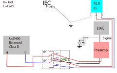
And then the only connection made to chassis by this audio ground is through a resistor capacitor network as shown in my updated diagram below. And this is to ensure that the common ground is at least somewhere near the operating range of the Amplifier for differential amplification.
Can someone confirm this? And would it be an idea just to make this RC connection to chassis at the common point where I am joining the two regulator OV's to? Then there is no need to make this connection from the signaling cable that I use to connect the signals up internally?
And can I just check my parts bin for values close to 100nf and 100 ohms for the RC connection to chassis?
Stu
http://www.hypex.nl/docs/appnotes/pin1_appnote.pdf
I will follow AES48 rules. My limited understanding of electronics was not enough to see how I could float my entire Raspberry Pi and Dac and Preamp source that is contained within the amp enclosure. Of course I will just treat it look an RCA input and I will follow the digram in 4.5 of the pin1_appnote.pdf.
So, I have two transformers supplying my TPS7A4700 regulator boards, the common outputs 0V of these will be connected together so that both supplies for the Pi Dac and Premamp are at the same common voltage.
And then the only connection made to chassis by this audio ground is through a resistor capacitor network as shown in my updated diagram below. And this is to ensure that the common ground is at least somewhere near the operating range of the Amplifier for differential amplification.
Can someone confirm this? And would it be an idea just to make this RC connection to chassis at the common point where I am joining the two regulator OV's to? Then there is no need to make this connection from the signaling cable that I use to connect the signals up internally?
And can I just check my parts bin for values close to 100nf and 100 ohms for the RC connection to chassis?
Stu
Attachments
Still no.
Connect the Mains PE direct to chassis permanently and near the IEC input socket.
Connect the XLR Pin1 direct to chassis at the socket. Hypex correctly says
If you want/need to make a safety connection from Audio ground to Chassis to comply with
That fault Current can exceed kA (>1000Apk).
Any resistor in that path will blow up and break the safety connection.
You must use either a direct wire connection, or use a Disconnecting Network that you know can safely pass that Fault Current.
Try finding a test report from any Member on any Disconnecting Network, or ground loop breaker, or ground lift/er.
As far as I know I am the only Member to get brave enough to test a Disconnecting Network and post the result.
Connect the Mains PE direct to chassis permanently and near the IEC input socket.
Connect the XLR Pin1 direct to chassis at the socket. Hypex correctly says
Follow that, The important part is shortest possible wire. It MUST be very low impedance and that is particularly referring to inductance.The best solution of course would be to open the faulty box, disconnect pin 1 from the circuit
board and connect it to the chassis with the shortest possible wire.
That fixes the problem at its root.
If you want/need to make a safety connection from Audio ground to Chassis to comply with
then that route MUST be able to pass Fault Current to PE."all exposed conductive parts should be connected to the PE protected chassis".
That fault Current can exceed kA (>1000Apk).
Any resistor in that path will blow up and break the safety connection.
You must use either a direct wire connection, or use a Disconnecting Network that you know can safely pass that Fault Current.
Try finding a test report from any Member on any Disconnecting Network, or ground loop breaker, or ground lift/er.
As far as I know I am the only Member to get brave enough to test a Disconnecting Network and post the result.
Last edited:
- Status
- Not open for further replies.
- Home
- Source & Line
- Analog Line Level
- Signal to chassis ground query