At least you have plenty of company here on diyAudio. 🙂(Instantly feeling like old Pawnshop or Salvation Army store material)
Even thirty years ago, I don't think I ever met an electronics engineer who knew that the small-signal voltage gain you get from a fully-bypassed common emitter BJT stage, is almost directly proportional to the DC voltage drop across the collector resistor.*
(*at low currents,, for voltage gains low enough that the slope of the Ic/Vce curves can be treated as zero.)
Today? I'm not in the industry any longer, but the electronics students and teachers I meet think that everything is a pulse or a square wave, and the only use for a transistor is to switch something on and off. They have never seen a circuit that has less than several tens of thousands of transistors in it (inside an IC, of course).
Let's face it: those of us who don't get Botox injected into our faces, spend over ten thousand dollars a year on fast-fashion clothing, and spend at least five hours a day on Facebook, Twitter, Instagram, Tik Tok, and Tinder, are old relics. We are irrelevant to the new order, where appearance is everything, and reality is optional. 😀
-Gnobuddy

Obviuosly you did not meet me. This knowledge was available since the early seventies to me by studying the one and only relevant text book named "Halbleiterschaltungstechnik" written by Tietze-Schenk. For those who want to understand disctrete analogue semiconductor circuitry this is a must. And I think there always have been people with a background far beyond your personal bubble.At least you have plenty of company here on diyAudio. 🙂
Even thirty years ago, I don't think I ever met an electronics engineer who knew that the small-signal voltage gain you get from a fully-bypassed common emitter BJT stage, is almost directly proportional to the DC voltage drop across the collector resistor.*
😀
-Gnobuddy
Maybe you live in your own personal bubble? 😉Obviuosly you did not meet me 😱 .... the one and only relevant text book named "Halbleiterschaltungstechnik" written by Tietze-Schenk. ...... far beyond your personal bubble.
I live at the other end of the World and also here Analog Electronics were only given the briefest treatment, as if "by obligation", before being given the full treatment of "the only important thing in the World", the newfangled Digital World.
We are talking Engineering Faculties, both at Universidad Católica (an expensive private institution) and Buenos Aires State University and starting in 1969 ... so I guess that was a Worldwide trend.
Gling indeed...
I remember in the guitar forum at DEC - maybe 30 years ago - someone had a SS preamp design, using FETs of course, which had the attribute that it could bark; something in context I believe only a tube amp was known to do. I dont know what you'd play on the guitar to evoke the bark sound, nevermind knowing what tube amps did this. Maybe whatever FZ did just following JLP's solo...with that "get out of my way" implication.
I recall reading others were suitably impressed it could do that, via a SS design.
When I played bass, I loved, loved my compressor. It'd let me do those long sustains, musically like using an organ pedal. And it held 99% of the time until I'd have to change to the next note anyway, so that opened up another dimension with which to play in. Didnt seem to squash the dynamics that much, for the sustain advantage.
An excellent word, don't you think? 😀Gling indeed...
Too bad mjd_tech's account is no longer active, so he can't come over here and take credit for his word.
While I don't know exactly what that word was originally used to describe, I do get the picture. Like "gling", "bark" does kind describe something I've heard from rock guitarists.... a SS preamp design, using FETs of course, which had the attribute that it could bark
My 2012 Dodge minivan left the factory with a state of the art audio system - for 2002. 🙄 It can only play CDs.
For a while now I've had a Gary Moore CD in there.
Recently my wife and I were driving somewhere when she commented that Moore was making his guitar snarl or growl in between notes, and that those growls really added a lot of emotional intensity to his playing.
I hadn't really noticed that until then, but she's absolutely right. In between long, singing, sustained notes, Moore would do something that would make the guitar emit a brief angry growl or snarl.
For instance, you can hear it clearly 49 seconds into this You Tube video of "Parisienne Walkways":
Moore starts to play the intro in earnest at around 37 seconds into the clip. At 49 seconds you can hear a "growl" from his guitar. Watch the video, and you can see Moore lift his fingertips off the fretboard briefly, letting all the strings ring out simultaneously, creating that aggressive growling sound.
You can hear the same growl several times during the guitar solos on that song. The version of the song on the CD in my car has even more "growling" than this live version.
Most guitarists who play with a lot of distortion and gain go to great lengths to mute all the unplayed strings all the time, to prevent them from making nasty noises. Here we see Gary Moore doing exactly the opposite - deliberately UN-muting all the strings to create those animalistic growls.
Do you know where we can see a schematic for the compressor section of your bass rig? It'd be interesting to see what sort of compressor that was.When I played bass, I loved, loved my compressor. It'd let me do those long sustains, musically like using an organ pedal.
Some decades ago, Signetics made an excellent compander chip, the NE571. What made it work really well was a very sophisticated circuit for sensing signal level accurately. If I remember right, it was a true-RMS circuit that could work over the entire audio frequency band and the entire dynamic range of audio signals.
The same chip could be set up to compress a signal, or to expand it. In compression mode, a 6 dB change in input level would result in a 3 dB change in output level - over the entire frequency and amplitude range of the music. There was no threshold or "knee", as we find in 99% of compressors.
In expansion mode, you got exactly the opposite: a 3dB level change at the input would create a 6 dB change at the output, over the entire frequency and dynamic range.
For use with tape decks, you could do even better. You could compress the signal you were recording onto the tape, avoiding tape saturation at the loud end, and tape hiss at the quiet end. Then, on playback, expand the signal to recreate all the original dynamics.
The NE571 in expansion mode could accurately undo what it did in compression mode, so the end result was apparently quite transparent (no audible traces of compression or expansion), only with much better S/N ratio.
The NE571 has been out of production for decades, but it would probably make it easy to create a really good bass compressor.
-Gnobuddy
I'm pretty sure it was just an MXR M102 "Dynacomp" pedal, being almost 30 years ago when I had and used it. Schematic should be easy to find; the used pedals certainly are!Do you know where we can see a schematic for the compressor section of your bass rig?
There's a nice schematic here (clickable link): http://www.generalguitargadgets.com/effects-projects/compression/mxr-dynacomp/I'm pretty sure it was just an MXR M102 "Dynacomp" pedal <snip>
It's all discrete BJTs (less harsh than op-amps driven into clipping), and an OTA (the ubiquitous CA3080) for the actual compression.
The full-wave rectifier circuit in the Dynacomp is clever. One transistor is used to generate two antiphase signals, each signal is half-wave rectified with a single diode, and the resulting two half-wave-rectified signals summed to create a single full-wave rectified signal.
Based on my own experiences, I have the impression bass guitars are more forgiving of compressor misbehaviour than regular (tenor) guitars are. Maybe because the lower frequencies from a bass give the rectifier / envelope detector more time to get a handle on things.
The optical compressor in my little ART Tube MP ( https://artproaudio.com/product/tube-mp-the-original/ ) is well behaved with my bass guitars, but prone to the odd popping sound when compressing signals from vocal mics or (tenor) e-guitars.
IMO, if I turn up the compression too much, it does squeeze a lot of life out of the sound of the bass. But in a busy mix the increased sustain and more consistent signal level might still be worth it.
-Gnobuddy
I have one of those and use it often. I really like what it does and wish I had a second one, actually - one for guitar, one for vocal. I'd like to put it on a pedal board with 12VDC available, but...it's 9VAC in. I've seen Xantrex makes sine wave 110V inverters, but expensive because everyone wants one - everywhere they are sold. Must be something to that nice clean synthetically generated AC power. Hopefully I'll get that challenge solved one day - till then I suppose I'll limp along with some ? brand stomp box compressor for that 12V powered speaker.The optical compressor in my little ART Tube MP
If it's of any interest, the Traynor Bloc 40B (or 80B) is a discrete design similar to the Bloc 100G, but simpler ''single channel'' for Bass guitar. They use a fixed bias on the first stage Jfet (which could be adapted to self bias), then through a passive tone stack, then on to the Jfet-PNP pair. ccording to the manual, overall voltage gain of the preamp is about 75 (using the low input sensitivity value 40mV) at max gain output about 3 Vrms. The preamp section is all run on a single voltage rail of 27 VDC, and I don't think it would be a problem to drop that down to 24 VDC for example. If this were run into a Class D power amp, it would probably benefit from some sort of limiter circuitry.
The voltage gain of the Jfet-PNP pair (also referred to as a compound series-feedback circuit) is set by the ratio of resistor connected from the PNP collector to the Jfet source and the Source to ground resistance. In the case of the Bloc 40B that is 47K/1.5K so it should be about 30. That leaves us with a gain of around 2.5 for the input fet stage, which sounds reasonable. It could be made higher at the input, but so long as the chosen Jfet isn`t too noisy that should be enough to feed the passive tone network on the design. As the 2N5485 is no longer available, I think with some adjustment to the source resistors it could work well with J111, J112, J113 types. 2N5457 could work but I would feel better running them at somewhere around 18 to 20 Volts supply.
It's conceivable that 9V AC input power is stepped up using a 60 Hz transformer for the 12AX7 stage, but it seems very improbable.I'd like to put it on a pedal board with 12VDC available, but...it's 9VAC in.
I wonder if it would run with 9V DC power (standard FX pedal power supply), or really needs it to be AC?
I like these little ART Tube MP gizmos a lot, too. They're a really nice Swiss Army Knife tool for coping with a variety of live-sound audio problems.
For a brief while we had a singer in our jam group who liked to alternately whisper and then scream at the top of her voice. If I turned down her mic she'd complain she couldn't her her whispers, if I turned it up, her screams gave the rest of us headaches.
An ART Tube MP set to brick-wall limiter mode solved the problem. I set her mic sensitive enough so she could hear her own whispers, but the limiter clamped down on her screams and kept them from taking our heads off.
Somewhere on Rod Elliott's website there is a very, very simple circuit for an LDR/LED compressor for bass, which works in conjunction with the existing power amplifier. Here you go: https://www.sound-au.com/project45.htm
-Gnobuddy
I just realized I posted an incorrect link to the ART Tube MPs that I have.
The ones I have look almost exactly like this: https://artproaudio.com/product/tube-mp-project-series-w-usb/
But they do not have USB.
I guess the model I have is out of production.
-Gnobuddy
The ones I have look almost exactly like this: https://artproaudio.com/product/tube-mp-project-series-w-usb/
But they do not have USB.
I guess the model I have is out of production.
-Gnobuddy
Essentially the same as the textbook non-inverting op-amp stage, except for having much less open-loop gain. And therefore, we hope, much less rude clipping behaviour. 🙂The voltage gain of the Jfet-PNP pair (also referred to as a compound series-feedback circuit) is set by the ratio of resistor connected from the PNP collector to the Jfet source and the Source to ground resistance.
I built a simple JFET stage for a guitar cab simulator I designed and built a couple of years ago. It was designed to run on 18V. I used a J112 because I had a few, and the datasheet promised some intriguing results....gain of around 2.5 for the input fet stage...
<snip>
...with some adjustment to the source resistor...it could work well with J111, J112, J113 types.
That particular J112 biased up nicely with an 8.2k source resistor at a Vgs which I thought was a good value to cope with a guitar signal without clipping (I don't recall the actual value, and forgot to write it down).
The source resistor was fully bypassed with a cap (10 uF, IIRC).
With a signal generator connected to the input, I found that a 22k drain resistor produced maximum ouput headroom before clipping. (The waveform was significantly distorted long before clipping, so I couldn't calculate this - the device isn't even close to linear.)
I also forget the measured drain current, but I think it was around 250 - 400 uA. Quite small.
(Centre-biasing was not the way to get maximum output headroom, because of the significant nonlinearity).
One noticeably big difference from more traditional JFETs was that the J112 stage had far more voltage gain. I got a voltage gain of x35 times (+31 dB) from that one single stage! That's at least triple what one would expect from older JFET devices.
The datasheet I found didn't even list the transconductance, but one can work that out from the slope of the curves. Transconductance remains high even at low drain currents. IIRC it was around 1.5 mA/V even at the small drain current at which the stage was operating.
With a 22k drain load, theoretical voltage gain (Av = gm Rd) is x33. No wonder I measured a small-signal voltage gain of x35!
The second big difference from all other JFETs I'd used in the past, was the surprisingly large amount of nonlinearity. The attached image came from a USB oscilloscope I was using at the time (it's measured data, not a simulation).
These J11x FETs were designed for switching, not for linear amplification, which probably explains why they distort so much when you try to build a linear amplifier with one.
(Which, of course, might be a good thing for use with e-guitar!)
The attached 'scope capture was taken with the output signal just short of clipping - all that nonlinear distortion came from the JFET transfer function, not because of any actual clipping caused by running out of voltage.
There's lots of distortion, but no sharp corners or flat-topped waveforms to be seen. This should produce pleasant-sounding, low-order harmonic distortion, exactly what we want with e-guitar.
I was using a 10x 'scope probe, so the approximately 1.2V peak-to-peak signal in the image translates to about 12 volts peak to peak at the drain of the J112.
Power supply was 18 V, so this is reasonable, given the need for some voltage across the source resistor, and some across the JFET channel itself.
-Gnobuddy
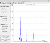
Edit: I remembered taking an FFT of the JFET output waveform, so I'm attaching that as well. Lots of 2nd harmonic, a splash of 3rd harmonic, very little 4th harmonic...just the sort of thing that should suit e-guitar very well!
Attachments
Last edited:
Interesting data on the J11x series, that is some large voltage gain you got there! You probably would have more than enough with just a couple of those and not need the Jfet-PNP.Essentially the same as the textbook non-inverting op-amp stage, except for having much less open-loop gain. And therefore, we hope, much less rude clipping behaviour. 🙂
I built a simple JFET stage for a guitar cab simulator I designed and built a couple of years ago. It was designed to run on 18V. I used a J112 because I had a few, and the datasheet promised some intriguing results.
That particular J112 biased up nicely with an 8.2k source resistor at a Vgs which I thought was a good value to cope with a guitar signal without clipping (I don't recall the actual value, and forgot to write it down).
The source resistor was fully bypassed with a cap (10 uF, IIRC).
With a signal generator connected to the input, I found that a 22k drain resistor produced maximum ouput headroom before clipping. (The waveform was significantly distorted long before clipping, so I couldn't calculate this - the device isn't even close to linear.)
I also forget the measured drain current, but I think it was around 250 - 400 uA. Quite small.
(Centre-biasing was not the way to get maximum output headroom, because of the significant nonlinearity).
One noticeably big difference from more traditional JFETs was that the J112 stage had far more voltage gain. I got a voltage gain of x35 times (+31 dB) from that one single stage! That's at least triple what one would expect from older JFET devices.
The datasheet I found didn't even list the transconductance, but one can work that out from the slope of the curves. Transconductance remains high even at low drain currents. IIRC it was around 1.5 mA/V even at the small drain current at which the stage was operating.
With a 22k drain load, theoretical voltage gain (Av = gm Rd) is x33. No wonder I measured a small-signal voltage gain of x35!
The second big difference from all other JFETs I'd used in the past, was the surprisingly large amount of nonlinearity. The attached image came from a USB oscilloscope I was using at the time (it's measured data, not a simulation).
That's the theory, and if you have a lower gm JFet, the PNP following should give a good gain boost..if the rail voltage is high enough it should stay away from clipping hard.Essentially the same as the textbook non-inverting op-amp stage, except for having much less open-loop gain. And therefore, we hope, much less rude clipping behaviour.
Not really.Essentially the same as the textbook non-inverting op-amp stage, except for having much less open-loop gain. And therefore, we hope, much less rude clipping behaviour.
The Op Amp has infinite gain and is reduced to the actual one by NFB, meaning it always has huge feedback for any reasonable gain.
Which means it will be very linear (it is being forced to by NFB) and will brutally clip because with no output voltage variation (hitting a rail) there is no NFB possible, so it becomes open loop and it hits those rails with a fury.
While the FET has NO NFB loop, all nonlinearities appear unhindered, and when it´s running out of stamina near each rail will simply curve waveform.
Completely different mechanism, clearly shown by scoping.
That in both cases resistors set gain, does not mean they work the same way, at all.
Test it yourself: build a, say, 20X gain FET stage and a 20X gain Op Amp one and drive both to clipping.
Compare waveforms, run FFT, the works.
Hi JM, I think Gnobody was originally commenting on that Jfet-PNP transistor pair in the Bloc 40B circuit with ''compound series feedback''. It would be interesting to compare that one with an op amp performance. With lower open loop gain and some local feedback from the PNP collector back through the source resistor. It could well be more linear than a fet on its own, but maybe not quite as ''perfect'' as an op amp...While the FET has NO NFB loop
Thank you, yes, exactly.Hi JM, I think Gnobody was originally commenting on that Jfet-PNP transistor pair in the Bloc 40B circuit with ''compound series feedback''.
The JFET-PNP pair is a voltage gain block, with the output voltage sensed by a feedback resistor, and the feedback voltage applied in series with the input voltage. The topology is the same as an op-amp in non-inverting configuration. "Series voltage negative feedback" if you use the textbook name for it.
I remember an old Phillips textbook on Hi-Fi audio electronics based around the then-newfangled silicon small-signal planar epitaxial transistors (BC147, 148, 149, 157, 158, 159). Every (Hi-Fi) preamplifier in the book was built around a direct-coupled transistor pair, with negative feedback from the collector of the second to the emitter of the first, in exactly the same configuration we're discussing (series voltage feedback).
That particular type of direct-coupled transistor pair also used a second DC feedback loop to bias the transistors into their operating regime, running from the emitter of the second transistor back to the base of the first one.
I mention this only because I think this sort of circuit topology was very much in the minds of audio electronics engineers at the time. It is a small step from the Phillips circuit to the Traynor one, simply replacing the first BJT with a JFET, and tweaking a few resistor values.
That's exactly what I was wondering, too!It could well be more linear than a fet on its own, but maybe not quite as ''perfect'' as an op amp...
The little J112 preamp stage I built had far too much distortion to emulate a (tube) triode stage for clean tone. I think it will probably sound a lot less "rude" than, say, a Tube Screamer, but a lot less clean than an actual vacuum triode.
A "proper" op-amp, on the other hand, has far too little distortion to emulate a tube, and, as JMFahey just said, it clips in a very ugly way.
Maybe the JFET/BJT pair is in a sweet spot somewhere in between? Just a few percent low-order distortion, and reasonably well behaved clipping?
I would knock up an LTSpice simulation, but it's a busy day, and it's going to be a busy evening, too.
-Gnobuddy
Oh, we are on the same page exactly. No disagreement at all. You just misunderstood which circuit I was speaking about earlier.Test it yourself: build a, say, 20X gain FET stage and a 20X gain Op Amp one and drive both to clipping.
Compare waveforms, run FFT, the works.
In my recent thread about clipping behaviour in solid-state preamps, I went to some trouble to find ways to demonstrate just how badly an op-amp behaves as an input stage for an electric guitar, especially when running on only 9 volts DC.
-Gnobuddy
- Home
- Live Sound
- Instruments and Amps
- Sidegig Guitar EVM from Texas Instruments thoughts?