Don't feed the troll.When you are interrogating someone and that person says he has sustaining evidence, then you ask him to cite it and he says "it's in the discussion we had earlier in my opinion", you take him seriously, right?
Sent from my phone with Tapatalk. Please excuse any typpos.
Don't feed the troll.
Sent from my phone with Tapatalk. Please excuse any typpos.
I'm not trolling I did pose a serious assumption and sought for opinions in this forum that's all. Most of the reactions were serious and some even hostile and unsympathetic like yours. Well if it makes you feel good and popular just go on.
Seriously you made your point I seems that I was an error believing that the front-endboard is the most important item in amplifier. I probably used the term sustaining and it should be circumstantial (was corrected before of not being an English native speaker). Hope you can forgive my naivitivity in this matter.When you are interrogating someone and that person says he has sustaining evidence, then you ask him to cite it and he says "it's in the discussion we had earlier in my opinion", you take him seriously, right?
I enjoyed Nelson Pass's talk at Burning Amp 2016, in which he explained that he liked to listen to power amp output stages, all by themselves, with no "front end" at all. He showed several circuits that let him do exactly this, for a few different output stages both conventional and unconventional. Nelson seems convinced that output stages have detectable sonic signatures; some sound better than others. He even described an experiment he did with his partner at Threshold, where he gave the guy two identical amplifiers in identical chassis and asked his partner to listen to both & see which was preferable. The difference? One had emitter resistors in the output stage, the other did not. Both Nelson and his partner preferred the sound of the latter. All else was equal!
I'm not trolling I did pose a serious assumption and sought for opinions in this forum that's all. Most of the reactions were serious and some even hostile and unsympathetic like yours. Well if it makes you feel good and popular just go on.
People can be rough around here sometimes. Helps to be a bit thick skinned.
Yes I've noticed but one must always be willing to alter ones opinion if valid arguments are brought against it. Maybe I persisted too long and people got annoyed about it. That's how it works in life.People can be rough around here sometimes. Helps to be a bit thick skinned.
I really believed that every thing in front of the drivers in terms of the schematic, the design mattered the most, but I was wrong and my assumption illformed. Thanks for your kind words.
Yes I've noticed but one must always be willing to alter ones opinion if valid arguments are brought against it.
Not sure that "opinion" and "valid arguments" are what are at issue, or should be at issue, in science and engineering. In law, yes. Totally different fields in terms of what may be held to be truth.
one had emitter resistors in the output stage, the other did not. Both Nelson and his partner preferred the sound of the latter. All else was equal!
It is not easy to make 'all else being equal'. I always avoid the resistors but that affects the frontend design. Worse, often there is an optimum amount of resistance in certain circuit, not too high, not too low. I was amazed the first time i found out about this (thinking that the difference should be inaudible)
Whether the resistors are necessary would depend on what output stage topology is used. If CFP with optimum bias to eliminate crossover distortion then the resistors are necessary. I suspect for CFP with 'first watt' bias and all darlington outputs that the resistors are not necessary, as for these there is no optimum bias; you just have to decide where you want to put the crossover glitches as you can't get rid of them.
Having said that, there is no accounting for taste so some people might prefer more distortion.
Having said that, there is no accounting for taste so some people might prefer more distortion.
Feedback caps
Bit of topic:
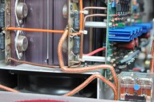
On the schematic of my amplifier there are two feedback caps (C2 & C3. 1000uF). I do know that these 1000uF original darkred Roedersteins (see pic)tend to dry out and it would be good practice to subtitute them with new ones, I bought four new Panasonics FM 5000uF but be honest I do not know how the work in this schematic. Somebody told me the value in F dictates the cut-off frequency and the higher the value the lower this cut-off frequency and it would enhance the bass of the amp. Can anybody explain to me how it works and how important these two capacitors (or maybe also the parallel .1 uF Film cap) are.
Thanks in advance.http://www.diyaudio.com/forums/atta...=599431&stc=1&d=1487162737&stc=1&d=1487162621
Bit of topic:
On the schematic of my amplifier there are two feedback caps (C2 & C3. 1000uF). I do know that these 1000uF original darkred Roedersteins (see pic)tend to dry out and it would be good practice to subtitute them with new ones, I bought four new Panasonics FM 5000uF but be honest I do not know how the work in this schematic. Somebody told me the value in F dictates the cut-off frequency and the higher the value the lower this cut-off frequency and it would enhance the bass of the amp. Can anybody explain to me how it works and how important these two capacitors (or maybe also the parallel .1 uF Film cap) are.
Thanks in advance.http://www.diyaudio.com/forums/atta...=599431&stc=1&d=1487162737&stc=1&d=1487162621
Attachments
Yes I've noticed but one must always be willing to alter ones opinion if valid arguments are brought against it. Maybe I persisted too long and people got annoyed about it. That's how it works in life.
I really believed that every thing in front of the drivers in terms of the schematic, the design mattered the most, but I was wrong and my assumption illformed. Thanks for your kind words.
Robert,
It is not often here that someone has the guts and intellectual honesty to change their mind and admit it. Chapeau.
Jan
On the schematic of my amplifier there are two feedback caps (C2 & C3. 1000uF)
These caps are in the feedback network to lower the amplifier gain to 1 at DC.
This is done so input stage DC offset does not appear at the output multiplied by the whole amplifier gain, but only with a gain of 1.
Value is not critical as long as it is large enough. The caps you picked will work just fine.
Bit of topic:
On the schematic of my amplifier there are two feedback caps (C2 & C3. 1000uF). I do know that these 1000uF original darkred Roedersteins (see pic)tend to dry out and it would be good practice to subtitute them with new ones, I bought four new Panasonics FM 5000uF but be honest I do not know how the work in this schematic. Somebody told me the value in F dictates the cut-off frequency and the higher the value the lower this cut-off frequency and it would enhance the bass of the amp. Can anybody explain to me how it works and how important these two capacitors (or maybe also the parallel .1 uF Film cap) are.
Thanks in advance.http://www.diyaudio.com/forums/atta...=599431&stc=1&d=1487162737&stc=1&d=1487162621
From a quick look at the schematic, the capacitors you are talking about set the time it takes for any DC offset at the output at the amplifier to be servoed out. This happens at below audio frequencies. Increasing the capacitors by a factor of five would be expected to make the DC servo five times slower. Maybe not a good idea depending on how fast the output offset drifts with temperature variations of the output transistors and other parts of the circuitry during normal operation.
Generally speaking, its probably not wise to substitute parts of different values with original parts without doing a careful analysis of the expected consequences. What I told you is just off the top of my head, and insufficient to make a good decision.
EDIT: The smaller cap is there because the electrolytics have high impedance at high frequencies, thus at 100kHz, for example, they are not good capacitors. Therefore, at high frequencies a good low impedance path is provided by the smaller capacitor.
Last edited:
Does sound large for a dc blocking negative feedback cap in the first place. Don't go any larger
i bought four new Panasonics FM 5000uF
Higher capacitance will have lower bass respons. But it is not wise going too high as the effect on sound will not be preferrable (higher internal inductance). In your amp, 470uf is fine. 2x 1000uf in series will form 500uf bipolar. Bipolar is expected to be better than a single 470uf. So replacing this with 5000uf will degrade the sound.
I dont usually parallel feedback cap with smaller value, unless i use low quality one, which i dont. The small cap might improve definition tho. I just prefer going with small pcb footprint.
The voltage on feedback cap is very small. I doubt that you need to replace it even if the internal temperature is very high.
- Status
- Not open for further replies.
- Home
- Member Areas
- The Lounge
- Shouldn't they all sound the same?