Design-wise, going to use PVC pipe as the basis. Matching that diameter about 100mm / 4". Sourcing the driver for that, Dayton Audio most likely. I have a contact in China that can source for me, so will take a look at what is available.
I thought Dayton stuff was made in Taiwan by Usher.
I tried to contact them locally a few times about this, but got nowhere.
Love the big horns, oh the things you could do with these. Like a choir of horns!
Check out the horns in my attached acoustic guitar patent.
Somewhat similar, let me know what you think! Have fun and keep going!
Check out the horns in my attached acoustic guitar patent.
Somewhat similar, let me know what you think! Have fun and keep going!
Joe,
Thanks for the links, the patents look good for a really cool instrument advancement. What a great technology to build into such a classic instrument.
Thanks for the encouragement as well! It feels a little lunatic but enjoying the learning process and idea evolution.
Thanks for the links, the patents look good for a really cool instrument advancement. What a great technology to build into such a classic instrument.
Thanks for the encouragement as well! It feels a little lunatic but enjoying the learning process and idea evolution.
I thought Dayton stuff was made in Taiwan by Usher.
I tried to contact them locally a few times about this, but got nowhere.
Perceval, am looking other similar options produced in China, pretty sure everything produced for Dayton Audio in China is exported. It may be a Taiwanese venture, but each (most all) speaker is stamped "made in China".
Love the big horns, oh the things you could do with these. Like a choir of horns!
Am imagining a group of these moving around in a big concrete skatepark with a wireless sync signal. Bouncing and concentrating sound. I am pretty sure the result would have a different name than choir 😀
Yeah a trumpet choir (as in angles) is probs too lame, more like the Devil's Army?
Do you have a patent on this device?
Do you have a patent on this device?
.. more like the Devil's Army?
Do you have a patent on this device?
Something in the middle ground. Reflectric Lite Orchestra, maybe 🙂
No patents. An evolved personal philosophy.
I have my name on many patents. Have challenged (when sued) and forced the cancellation of one due to pre-existing art. Have been involved in several patent litigations. At each conclusion, no one won except the law firms. That is nothing against lawyers, they do an awesome job.
This portable beaming concept will draw from a wide history and people's inputs thankfully. There will no doubt be unique patentable elements generated along the way, I don't see anything that could be established as a roadblock for other ideas. There are a dozen squared ways to skin a cat.
It is a passion project that has a narrow target audience. It will evolve and if there is any interest, others may build variations, and I will be inspired to build a better one. Competition makes ideas stronger.
I am confidently betting that Yamaha and Sony will never make one. 🙂 Even if they did, they could potentially bury me in litigation for decades with the deep pockets.
That's the short version.
Last edited:
freddi - that is pretty wild, good to see it covers so much area, encouraging!
stratotron - understand about the patent. I have one knowing that financial success is about 10% for a patent. I figured I would give it a try anyway. I did learn how to write patents myself (took two years to learn), so at least I don't have to pay a patent attorney!
stratotron - understand about the patent. I have one knowing that financial success is about 10% for a patent. I figured I would give it a try anyway. I did learn how to write patents myself (took two years to learn), so at least I don't have to pay a patent attorney!
hey Joe K
I know its not pertinent to this thread at least not directly, but its fascinating
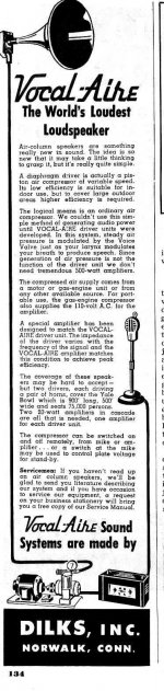
how the phonograph was amplified using compressed air before there were any vacuum tubes, magnetic pickups and moving coil speakers
Doug Self has a section
The Auxetophone.
Examples on YouTube
https://www.youtube.com/results?search_query=Auxetophone
I know its not pertinent to this thread at least not directly, but its fascinating
how the phonograph was amplified using compressed air before there were any vacuum tubes, magnetic pickups and moving coil speakers
Doug Self has a section
The Auxetophone.
Examples on YouTube
https://www.youtube.com/results?search_query=Auxetophone
Horn designs with compression drivers seem best suited to this task. Conical shapes seem to intuitively beam more than flared end shapes.
Depends on the desired BW, power handling desired, just if using a cone driver, use a driver suitable to handle a 2:1 compression ratio [CR] for overall optimal efficiency.
Hmm, what they do is collapse/'pinch' at the terminus unless at ~2/3 length it doesn't rapidly flare out with dispersion at ~ f = 10^6/[wall angle*terminus width] for a specific pattern; otherwise may find that it's better to have an inverse flare like the later version of the B0$3 wave cannon for 'point n' spray'.
Stratotron,Following Art's #14 post in extremely narrow directivity speaker design looking up Curtis Graber's Hyperspike patents in published documents. Very interesting approach.
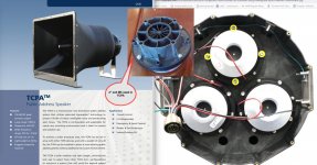
Large transducers in the production model. Appears to drive a piston-like plate moving air into the rim of the inverted horn?
The "piston-like plate" is probably not intended to move.
The three drivers appear to be individually driven, they may be the backs of Graber's M5 2" exit driver, which was "new" in 2013.
His "Radial waveguide for double cone transducers" patent application was in 2013.
The M5 uses a twisted radial phase plug aperture.
Using a tandem transducer compression phase plug and two M5 in the TCPA feeding complex waveguide/reflectors, it is capable of up to 147dBa 1m at full rated power of 500 watts.
Using DSP, three drivers individually driven could allow different beam patterns to digitally sculpt the acoustic beam without physically moving the projector.
Art
Attachments
Last edited:
I know its not pertinent to this thread at least not directly, but its fascinating
how the phonograph was amplified using compressed air before there were any vacuum tubes, magnetic pickups and moving coil speakers
Freddi, that is an amazing train of development, I had no idea it existed. Very interesting to see and chase those ideas through patents and the stories of the people that invented the technology.
Depends on the desired BW, power handling desired, just if using a cone driver, use a driver suitable to handle a 2:1 compression ratio [CR] for overall optimal efficiency.
Hmm, what they do is collapse/'pinch' at the terminus unless at ~2/3 length it doesn't rapidly flare out with dispersion at ~ f = 10^6/[wall angle*terminus width] for a specific pattern; otherwise may find that it's better to have an inverse flare like the later version of the B0$3 wave cannon for 'point n' spray'.
GM, Thanks for that input, I had not seen the Bose Wave Cannon before. I could not find any examples of later versions of it. Researching the references to inverse flares, which sounds in line with what I am experimenting with. Collapsing the terminus of the horn, are there notable approaches to look at?
Art, good eye on that, looks like that transducer indeed, thanks for connecting that. I see references to different radial zones around the central spike in his patents, cannot figure out how that would have an effect radially. The only conclusion I have come to is that it would allow for mode painful high concentration nodes.The three drivers appear to be individually driven, they may be the backs of Graber's M5 2" exit driver, which was "new" in 2013.
His "Radial waveguide for double cone transducers" patent application was in 2013.
Shoulder Slung Synth Beamer, prototype 1 of 3, SSSB-A
The parts for the first design shoulder-slung synth beamer prototype arrived. The design was started before I had awareness of horn and waveguide theory.
The design was derived from the original 80s model seen at a live performance. The original was a speaker mounted at the rear of a straight acrylic tube with no shaping. At first tests with a PVC pipe, the 80s design was very resonant hollow sounding.

In a modern recollection and rendering, the original looked about like this.
The SSSB-A prototype is designed to be modular, with swappable elements and flexible spacing, o-ring seals to hold distances. The original intent was to have the battery and amplifier inside the tube. Instead went for a bigger battery in a backpack and the tube is currently empty.

This is the render of the encapsulated system with a short horn.
These are the CNC'd parts assembled with a donor Onkyo speaker.


The differences in distance of the waveguide (two images below) have a marked effect on the sound, like an analog resonant filter, initially undesirable, but it opens a door to physical interactive filtering during live play. Interesting in a positive way. The modular design allows for inserting a phase plug between the cone and the horn, will experiment with that as well, thinking possibly interactive shaping might be possible.


As one might expect, the sound does not "project" at all with the short horn, the sound is spread and has weak LF. The optional longer-shaped guide insert design takes into consideration some theory. Here is the rendering.


Here is the quick working conical test, much better LF and directionality.

Size comparison with the paper mache horn (SSSB-B).

The parts for the first design shoulder-slung synth beamer prototype arrived. The design was started before I had awareness of horn and waveguide theory.
The design was derived from the original 80s model seen at a live performance. The original was a speaker mounted at the rear of a straight acrylic tube with no shaping. At first tests with a PVC pipe, the 80s design was very resonant hollow sounding.
In a modern recollection and rendering, the original looked about like this.
The SSSB-A prototype is designed to be modular, with swappable elements and flexible spacing, o-ring seals to hold distances. The original intent was to have the battery and amplifier inside the tube. Instead went for a bigger battery in a backpack and the tube is currently empty.
This is the render of the encapsulated system with a short horn.
These are the CNC'd parts assembled with a donor Onkyo speaker.
The differences in distance of the waveguide (two images below) have a marked effect on the sound, like an analog resonant filter, initially undesirable, but it opens a door to physical interactive filtering during live play. Interesting in a positive way. The modular design allows for inserting a phase plug between the cone and the horn, will experiment with that as well, thinking possibly interactive shaping might be possible.
As one might expect, the sound does not "project" at all with the short horn, the sound is spread and has weak LF. The optional longer-shaped guide insert design takes into consideration some theory. Here is the rendering.
Here is the quick working conical test, much better LF and directionality.
Size comparison with the paper mache horn (SSSB-B).
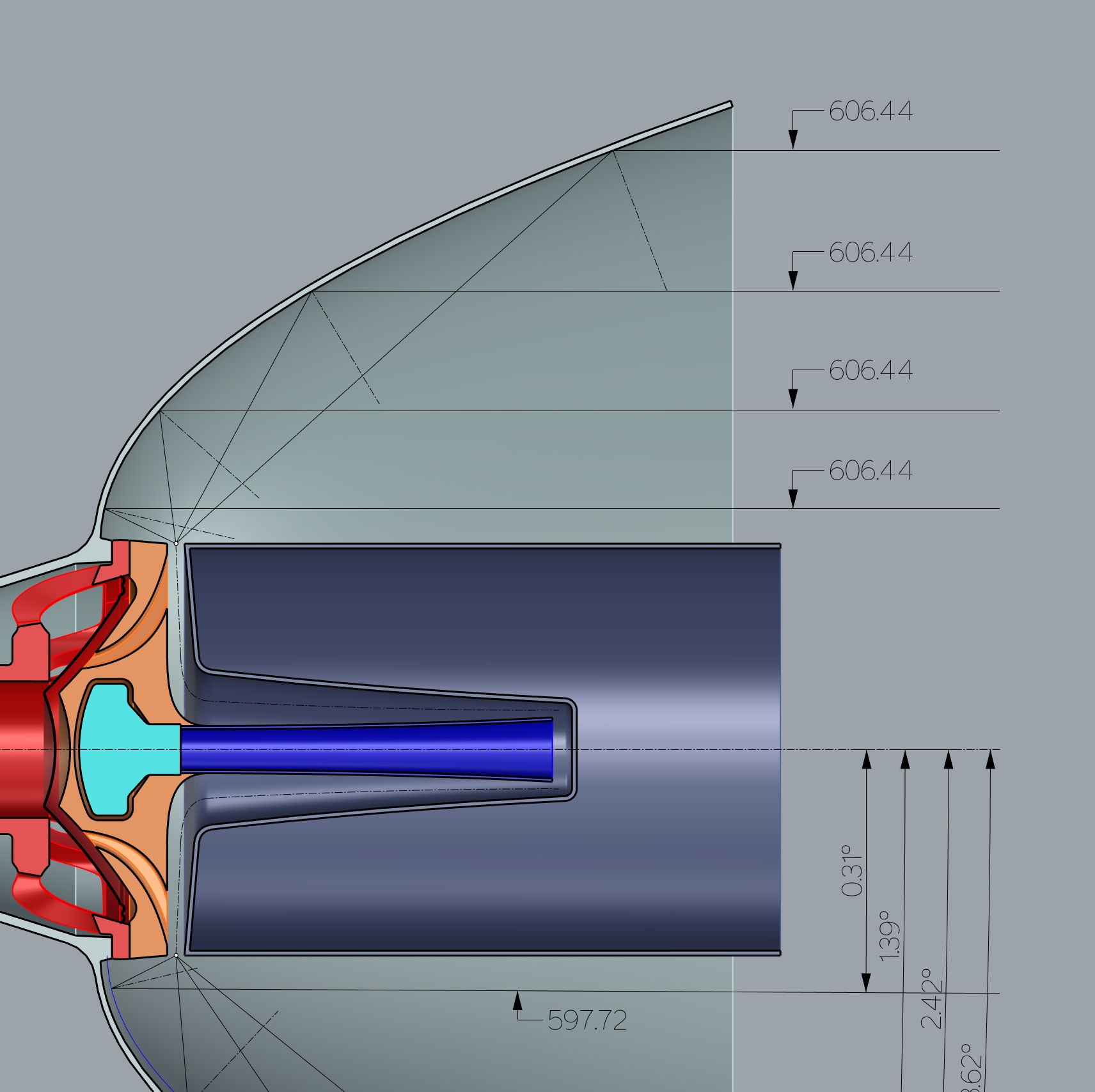
Shoulder Slung Synth Beamer, prototype 1 of 3, SSSB-C Parabolic
Midway through the construction of the third variation, SSSB-C. Parabolic reflector with internal radially directed sound waves. Elected for the first test not to use a megaphone, instead matching two speakers.
Two 6" speakers are mounted face to face between the wood cans. There is a 10mm space between the disks. Initially, no phase plug between the cones. The volume of the cans approximates the original boxes that the repurposed cones came from. A duplicate to OEM volume vent will be added along with the original HF cone in the forward-facing end, i.e. not directed into the parabola, facing straight out inside a small horn.

Diagram


Work in progress of the parabola form and initial paper mache application. The radial sound production is good out of the gap between the currently sealed cans.
Midway through the construction of the third variation, SSSB-C. Parabolic reflector with internal radially directed sound waves. Elected for the first test not to use a megaphone, instead matching two speakers.
Two 6" speakers are mounted face to face between the wood cans. There is a 10mm space between the disks. Initially, no phase plug between the cones. The volume of the cans approximates the original boxes that the repurposed cones came from. A duplicate to OEM volume vent will be added along with the original HF cone in the forward-facing end, i.e. not directed into the parabola, facing straight out inside a small horn.
Diagram
Work in progress of the parabola form and initial paper mache application. The radial sound production is good out of the gap between the currently sealed cans.
hum two slot loaded drivers at the wrong feed point to a parabolic....are you not wanting mid or high frequency content???
The feed point is the focus of the parabola. Shown in the upper section of the image. All lines drawn are exiting equal length and parallel. Is there a better location to feed from?
- Home
- Loudspeakers
- Full Range
- Shoulder slung, waveguide, synth beamer