Hi Tibi
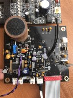
Been very busy here - no time to play with my toys. Finally got a bit of time so here are some pics of my lovely mess. As you can see because of all the work around V1 and ADP151 is looking messy. Embarrassing to have it displayed here for all to see 🙂
I am currently powering V1 from Zeno 5V. The extra green wire on the rear is link to GND because I broke that pad with too many install/uninstall procedures.
V2,3,4 all Vicol miniregs powered by Zeno 8V.
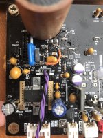
I have tried all the different implementations of ADP151 as per post#1819 (but not option 3). Both when using Zeno and when using LF50 reg. All combinations return the same result so I am of the opinion my fault does not reside around V1 and ADP151 implementation. I have not gone back to vanilla here ie. no ADP151.
From ADP151 I read 2.54v and at other side of L1 I read 2.51v
As previous I read TOC and play for 1-2 seconds before returning to index.
[Pictures to follow - I pressed submit then left the house. Looking at this post now on my phone I see pics did not upload. Will correct once I get home. Thanks.]
Been very busy here - no time to play with my toys. Finally got a bit of time so here are some pics of my lovely mess. As you can see because of all the work around V1 and ADP151 is looking messy. Embarrassing to have it displayed here for all to see 🙂
I am currently powering V1 from Zeno 5V. The extra green wire on the rear is link to GND because I broke that pad with too many install/uninstall procedures.
V2,3,4 all Vicol miniregs powered by Zeno 8V.
I have tried all the different implementations of ADP151 as per post#1819 (but not option 3). Both when using Zeno and when using LF50 reg. All combinations return the same result so I am of the opinion my fault does not reside around V1 and ADP151 implementation. I have not gone back to vanilla here ie. no ADP151.
From ADP151 I read 2.54v and at other side of L1 I read 2.51v
As previous I read TOC and play for 1-2 seconds before returning to index.
[Pictures to follow - I pressed submit then left the house. Looking at this post now on my phone I see pics did not upload. Will correct once I get home. Thanks.]
I need some detailed pictures, to see what you have down and how you have implemented.
Regards,
Tibi
Last edited:
Thanks for pictures !
I suggest you to add ADP151 input capacitor, 1uF ceramic and also add 1K resistor.
Other straps are not needed.
Regards,
Tibi
I suggest you to add ADP151 input capacitor, 1uF ceramic and also add 1K resistor.
Other straps are not needed.
Regards,
Tibi
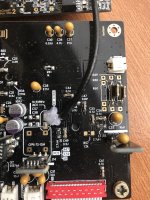
Do you mean C69? input capacitor? it is there
Do you mean C68? R65?
But with trace cut above U5 these no longer have electrical connection to U5?
I have 10uf tant and 1k parallel through hole on C11
Do you mean C68? R65?
But with trace cut above U5 these no longer have electrical connection to U5?
I have 10uf tant and 1k parallel through hole on C11
Thanks for pictures !
I suggest you to add ADP151 input capacitor, 1uF ceramic and also add 1K resistor.
Other straps are not needed.
Regards,
Tibi
Ok still no joy here!
Have removed all ADP151 components etc. Replaced L1
Gone back to using original Shiga psu and trafo
V1,2,3,4 all in range from 5.01v - 5.04v
Steady 2.54v across L1 and at pin58
Using a new vanilla mechanism and laser and new ribbon connector
Using Tentlabs XO
Laser pops up and down tracks across CD but DOES NOT READ TOC
Done everything that I have done in the past when I have had problems but cannot get this to work. I don't have a scope so can't give any readings like that. Just working with DMM. I get the feeling that I am missing something simple but what?.....
Do you mean C69? input capacitor? it is there
Do you mean C68? R65?
But with trace cut above U5 these no longer have electrical connection to U5?
I have 10uf tant and 1k parallel through hole on C11
I suggest you to clean the board with isopropylic alcohol and check if there is no pcb trace damaged.
Another issue may be that due excesive solder/desolder main IC's get one pin or more desoldered as well.
Resoldering main IC's may solve the problem.
Regards,
Tibi
Another issue may be that due excesive solder/desolder main IC's get one pin or more desoldered as well.
Resoldering main IC's may solve the problem.
Regards,
Tibi
Hi Tibi
Followed your most recent suggestions but no luck yet.
Traced continuity from each pin on ICs to nearest component (using Mk1 schematic as reference - I know there are some differences especially with labelling). All seem to check out fine.
So must have fried an IC? Otherwise I am all set to pull the mini regs etc. and go back to as close to zero mods as I can.
I suggest you to clean the board with isopropylic alcohol and check if there is no pcb trace damaged.
Another issue may be that due excesive solder/desolder main IC's get one pin or more desoldered as well.
Resoldering main IC's may solve the problem.
Regards,
Tibi
Hi all,
my shiga gives no sound any more.
I changed nothing, it just went from playing nicely one day to no sound another day.
i checked everything and all looks ok
voltages are all good
toc is fast and good, cd turns as normal and i can skipp songs as normal, everything behaves normal only no sound.
when i measure the spdif output it showes 0.51 Vdc and 0.025 Vac.
on another random cd player spdif measures at 0 Vdc and around 1.9 Vac.
anyone have an idea what to look for??
thanks in advance.
regards,
John.
John,
This is a s/pdif issue. There is very little to check. Cable and connectors are first.
Regards,
Tibi
This is a s/pdif issue. There is very little to check. Cable and connectors are first.
Regards,
Tibi
Tibi,
cables and connectors are good, no issues there.
if not that, what then?
regards,
John.
cables and connectors are good, no issues there.
if not that, what then?
regards,
John.
John,
s/pdif resistors, measure them and check solder joints.
Lastly, check signal on LC78601 pin 29 and re-solder.
Regards,
Tibi
s/pdif resistors, measure them and check solder joints.
Lastly, check signal on LC78601 pin 29 and re-solder.
Regards,
Tibi
Tibi,
the resistors measure 330r and 100r, solder joints are good.
pin 29 i measure 2.15Vdc and 0.026 Vac.
regards,
John
the resistors measure 330r and 100r, solder joints are good.
pin 29 i measure 2.15Vdc and 0.026 Vac.
regards,
John
This indicate me that your LC78601 output may be faulty. This may be caused by static discharge. Are your equipments earth grounded or at least enclosures connected to same potential ?
Regards,
Tibi
Regards,
Tibi
...
pin 29 i measure 2.15Vdc and 0.026 Vac.
regards,
John
John,
How do you measure this values ? Hope you are using an oscilloscope.
A multimeter will not measure at s/pdif frequency.
Regards,
Tibi
Tibi,
I measured with a normal multimeter, i do not own a scope.
I do have a fluke 867B that i dont trust since i doesnt measure dc and ohm anymore.
the fluke measured 0.84 Vac at 44.1kHz at pin 39, but like i said, not sure if that is correct.
regards,
John
I measured with a normal multimeter, i do not own a scope.
I do have a fluke 867B that i dont trust since i doesnt measure dc and ohm anymore.
the fluke measured 0.84 Vac at 44.1kHz at pin 39, but like i said, not sure if that is correct.
regards,
John
John,
Your multimeter should work at 2.8224 Mbit/s (bit rate) in order to measure s/pdif properly.
Regards,
Tibi
Your multimeter should work at 2.8224 Mbit/s (bit rate) in order to measure s/pdif properly.
Regards,
Tibi
Hi Tibi,
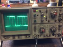
I managed to borrow a (very old) scope.
I dont really know what i am doing, but i got a signal.
pic1 at spdif out no music playing
pic2 at spdif out music playing
pic3 at pin 29 no music playing
pic4 at pin 29 music playing
regards,
John
I managed to borrow a (very old) scope.
I dont really know what i am doing, but i got a signal.
pic1 at spdif out no music playing
pic2 at spdif out music playing
pic3 at pin 29 no music playing
pic4 at pin 29 music playing
regards,
John
Attachments

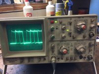
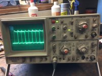
After a closer look, I see that at pin 29 you have on Chan1 0.5V/div while on connector output you have 50mV/div which is far too low. So this is obvious to me that there is a connector issue or something wrong with resistor divider.
Regards,
Tibi
Regards,
Tibi
- Home
- Source & Line
- Digital Source
- Shigaclone MKII Black - The builders Thread