Hi Steve,
While operating, Shiga will draw between 200mA no play and 400-800mA while playing. This variation is due motor speed etc.
Brgsd
While operating, Shiga will draw between 200mA no play and 400-800mA while playing. This variation is due motor speed etc.
Brgsd
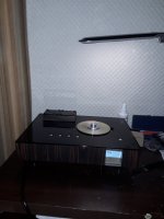
Need some help, I just finished transistioning shiga into a permanent case. I had not had operating for awhile as all parts were removed from breadboard to get layout in case. I did not re-assemble and test before mounting. Now I can not get laser to power on. I have 3 mechs, one purchased modded, one I modded, and one un-modded for testing. None will function properly. They try to read TOC and stops with -- -- on display. I have checked multiple times and all voltages look good.
Pin 1 vref-2.62Vdc
Pin 2 Com- 5.1Vdc
Pin 3 E - 2.58Vdc
Pin 4 D - 2.58Vdc
Pin 5 A - 2.58Vdc
Pin 6 B - 2.58Vdc
Pin 7 C - 2.58Vdc
Pin 8 F - 2.58Vdc
Pin 9 GND - yes
Pin 10 LD - 5.1Vdc
Pin 11 VR - GND to 9 yes
Pin 12 MD - 1.5Vdc
Pin 13 F+ - 3.7Vdc
Pin 14 T- - 3.7Vdc
Pin 15 T+ - 3.7Vdc
Pin 16 F- - 3.7Vdc
All motor functions appear to work as laser head will scan CD [BTL driver]
In a completely dark room I can not see or photograph any light from laser diode? [ NO BLOBS IN PLACE]
Any idea why laser is not working on any of these ? Would APC be functioning but some other issue cause this, I was hoping to not have to dissassemble again to get to IC's . Is a reset not happenning possibly?
best regards,
Steve
Hi all,
Still toubleshooting here. The laser transistor 2N4403 is what I am looking into now. I get 4.5v from LDD pin to base, emitter is 5Vdc as well as collector. .55Vdc E-B and C-B. I am having a hard time putting on scope as part is so close to board I can't get any clips on legs. I have these numbers from touching legs with jumper wire clipped to probe with power on only. If I can get a way to see when switching CD door what should I expect to see? I assume LDD should drop from 4.5vdc to switch on laser. [E-C] Thanks for any input. I am self taught on this stuff so any info is appreciated.
best regards,
Steve
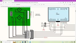
SO I can't figure this out. In image from schematic the pcb for motors starts on left [1] Gnd. Plug shows 1 grnd 2 switch 3 SL+ 4 SL- 5 SP- 6 SP+
Sanyo deck shows 1 GND 2 SW 3 SL+ 4 SL- 5 SP- 6 SP+. It appears sled +/- would be reversed if I just keep the ribbon cable in order!?
I did have mech functioning on breadboard for cd play & cd door, reverse track, NO forward track. Am I missing something or would this reverse +/_ sled.
thanks for any help
best regards,
Steve
Hello again. Trying to repeir my shiga.
Shiga dont read any cd. Motor, laser, focus looks like it works properly. I have change LA9242 and LC78601 chip, new laser. All v1,v2,v3,v4 have 5.01 -5.03 vdc and keeping it well.
I have measured cd decl pin out and when it stops but laser is connected i have;
Pin 1 vref-2.54
Pin 2 Com- 4.11
Pin 3 E - 2.54
Pin 4 D - 2.54
Pin 5 A - 2.54
Pin 6 B - 2.54
Pin 7 C - 2.54
Pin 8 F - 2.54
Pin 9 GND - yes
Pin 10 LD - 1.49
Pin 11 VR - GND to 9 yes
Pin 12 MD - 0.0
Pin 13 F+ - 3.6
Pin 14 T- - 3.63
Pin 15 T+ - 3.63
Pin 16 F- - 3.6
When i push cd door :
Pin 1 vref-2.54
Pin 2 Com- 4.11
Pin 3 E - 2.54
Pin 4 D - 2.54
Pin 5 A - 2.54
Pin 6 B - 2.54
Pin 7 C - 2.54
Pin 8 F - 2.54
Pin 9 GND - yes
Pin 10 LD - 1.49 to 2.24
Pin 11 VR - GND to 9 yes
Pin 12 MD - 0.0 to 0.10
Pin 13 F+ - 3.6 to 4.07
Pin 14 T- - 3.63 to 3.67
Pin 15 T+ - 3.63 to 3.66
Pin 16 F- - 3.6 to 4.02
And what is going on when i disconect laser:
Pin 1 vref-2.54
Pin 2 Com- 5.03
Pin 3 E - 2.51
Pin 4 D - 2.51
Pin 5 A - 2.51
Pin 6 B - 2.51
Pin 7 C - 2.51
Pin 8 F - 2.51
Pin 9 GND - yes
Pin 10 LD - 5.03
Pin 11 VR - GND to 9 yes
Pin 12 MD - 1.64
Pin 13 F+ - 3.58
Pin 14 T- - 3.61
Pin 15 T+ - 3.63
Pin 16 F- - 3.6
Please tel me where to search ? I have seen that i dont have 5v on two pins but 4.11v and this voltage is going from Q1 2N4403transistor .
Hello again. I have change LA9242 again. And shiga is alive! It reading how many track are and plaing for 10sek. I know that problem is in laser. New laser i had i have give to my friend. Old laser is an org sanyo but i have use an potentiometr near laser.. i know i have done wrong but i was try everything to start shiga working. This laser plays for 10 seconds. Please tell me how to adj laser properly. I have ans oscilosope but dont know where to connect and what i nead to se. Please help me.
Did any one compared orginal sanyo laser to chineese sfp101n one? It is hard to find sanyo one.
yeah I switched to check. I still cannot get laser to turn on 3 different mechs modified and unmodded. I get normal voltage readings but I wonder if I am not getting threshhold current to laser. Using Salas Reflektor D for 5 volts and should have plenty current output. I don't think I would have 5vdc at transistor and after [2N4403] but no current . I am not sure where to measure / to open circuit to get mA reading to laser diode? Anybody ever done this?
regards,
Steve
regards,
Steve
Hello , after 3 month, mayby 1 mont of playing chinese laser died. Music plays for 10 sec and i have problem with Read. What laser need to bay to play longer? It is hard to find an orginal sfp101n . Or what to do to play longer? im always do litle laser upgrade and change smd capacitors to silver mica caps like lots off people do. Please help me.
I have bay 2 not orginal lasers. One read only number of tracks, second plays mayby 3 second. What is goin on whit this lasers? Mayby something in projekt is adjust to much and delikate lasers are domageing? did any body have that problems witch lasers?
Hello! for those having laser problem can try Sony Laser Head KSS-213C, I am currently using this laser and it read CDR a lot better than the Sanyo laser.
Hello i dont know what is going on witch this lassers. I have bough next 3 lassers. After change shiga works perfect , first one played 1hour, when i power of cd and power on lasser have problem witch read. Seccond one played couple days.. i dont know what is killing them. on shiga pcb i have 4x 5.00v stabs, and 8v. 2.51v reference. Orginal lasser plays 3 months. This time i have new lasser and im not changing smd capacitors on it(when lassers work well i have change 3 smd capacitors for silver mica caps)
I can use just kss 213c laser head? or i must change all mechanics? i can see that slide side is little difrent in kss. And what about lasser optic distance to cd rom? I have measure that in sfp101n it is 19.2mm-20mmHello! for those having laser problem can try Sony Laser Head KSS-213C, I am currently using this laser and it read CDR a lot better than the Sanyo laser.
you have to change whole CD mechanism and modify the CD puck a bit (drill 3 mm hole at the center of the puck for about 4mm deep)

- Home
- Source & Line
- Digital Source
- Shigaclone MKII Black - The builders Thread