If I use the full sample rate of the the ADC to 192k I can get to 3kHz real time. After that under sampling must be used. For 3k to 6k the sampling would be spread over 2 cycles, for
6k to 12k the sampling would be spread over 4 cycle and so on. An Arduino or other PIC should work. A dsPIC can do simple integer DSP. I can try to use the SPI port for I2S but
a large shift register for buffer would be better. The buffer can run as a slave on the output side and run in a loop. This takes the weight off the processor from having to keep up.
Just load one cycle of samples into the buffer and let it run until an update is ready.
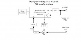
The PLL will be the tricky part.
It makes for an interesting experiment.
6k to 12k the sampling would be spread over 4 cycle and so on. An Arduino or other PIC should work. A dsPIC can do simple integer DSP. I can try to use the SPI port for I2S but
a large shift register for buffer would be better. The buffer can run as a slave on the output side and run in a loop. This takes the weight off the processor from having to keep up.
Just load one cycle of samples into the buffer and let it run until an update is ready.
The PLL will be the tricky part.
It makes for an interesting experiment.
You have two options. First is to reconstruct the signal with a DAC and do analog analysis. The other would be to do FFT directly on the sampled data. Even an Arduino could do that today if you don't expect real time to 100 KHz. Display of the output becomes pretty easy and flexible. I suspect the later Panasonic analyzers work this way.
"The other would be to do FFT directly on the sampled data."
Why add distortion, go direct.
I ordered the Minidsp USBExtreme for this purpose.
I'll get you details on the TI dsp chip that will sample to 768KHz. 16 bit only. Give me a day or two.
This is actually capable of 768 KHz sample rates http://www.ti.com/lit/ds/symlink/tlv320aic3254.pdf It has a lot of power but is not too DIY friendly. Its almost too small for humans to interact. . .
This is actually capable of 768 KHz sample rates http://www.ti.com/lit/ds/symlink/tlv320aic3254.pdf It has a lot of power but is not too DIY friendly. Its almost too small for humans to interact. . .
Thanks Demian.
I got the manual yesterday. Ill post scans and details when I can. No real surprises. The sampling is at 64X of the fundamental it uses some undersampling trick for higher frequencies sine the ADC is limited to 50nS sample clocks.
I got the manual yesterday. Ill post scans and details when I can. No real surprises. The sampling is at 64X of the fundamental it uses some undersampling trick for higher frequencies sine the ADC is limited to 50nS sample clocks.
50ns is 20Msps. Is this correct. I'll have to look at the BB data sheet for that again.
I don't understand the connection pin 10 of u2 'Q' to pin 8 of U8 which is labeled LF357. The data sheet for the LF357 show this pin 8 as a NC pin. Is pin 8 of the metal can version connected to the case? Is this a driven shield? If so why drive it with a rectangular pulse?
Last edited:
I have the factory schematics now. I'll scan them and post them this weekend. PChi's reverse engineering has been really good. The docs are pretty good but with some significant holes. The copy I got won't be the easiest to scan since its a less that great copy.
U8 (U13 on my print) is an LF398. Pin 8 is labeled logic on the print. U8 on the print is a 4049 hex inverter.
U8 (U13 on my print) is an LF398. Pin 8 is labeled logic on the print. U8 on the print is a 4049 hex inverter.
I have the factory schematics now. I'll scan them and post them this weekend. PChi's reverse engineering has been really good. The docs are pretty good but with some significant holes. The copy I got won't be the easiest to scan since its a less that great copy.
U8 (U13 on my print) is an LF398. Pin 8 is labeled logic on the print. U8 on the print is a 4049 hex inverter.
An LF398 makes more sense driven from a mono.
I'm particularly interested in the input frequency multiplication, PLL etc, section right now.
I'm wondering how Shibasoku manged the jitter. The jitter is multiplied by the frequency division of the counter/divider circuit. TI indicated as much as 5.5us in this paper
http://www.google.ca/url?sa=t&rct=j...6pFNOGaz8SBz8ZJhc6rn5MQ&bvm=bv.52434380,d.cGE
AD shows a modern advanced approach in this paper
http://www.google.ca/url?sa=t&rct=j...44DYCw&usg=AFQjCNElRDdDXP5E4cAdwpV1gPCrroVlHQ
This is a lot more expensive though but promises very low jitter.
Thanks for your effort Demian.
Attachments
Last edited:
Thanks for pointing out the error, just confirming that it is an LF398 sample and hold. My excuse is that I wrote LF398 on the first drawing and failed to write it correctly on the second drawing that I attached, my brain was elsewhere.I have the factory schematics now. I'll scan them and post them this weekend. PChi's reverse engineering has been really good. The docs are pretty good but with some significant holes. The copy I got won't be the easiest to scan since its a less that great copy.
U8 (U13 on my print) is an LF398. Pin 8 is labeled logic on the print. U8 on the print is a 4049 hex inverter.
Shibasoku 725B manual
I have scanned the main part of the manual and can share it. Please PM with your e-mail. The file is almost 3 MB. Too much to upload. It will have most of the important details. The schematics will take longer.
I have scanned the main part of the manual and can share it. Please PM with your e-mail. The file is almost 3 MB. Too much to upload. It will have most of the important details. The schematics will take longer.
FYI -
Since I also have a 725... I found a copy on eBay and it is being shipped to me for my reference. But its isnt the D version that I have. Same B version.
-RNM
Since I also have a 725... I found a copy on eBay and it is being shipped to me for my reference. But its isnt the D version that I have. Same B version.
-RNM
There is an error on the schematic sheet A10. QA2-2 pin 11 CLK line and QA7 pin 12 are tied together and floating.
I don't know if we can find anything more complex than the Shibasoku AG725 being built almost entirely from discrete logic components and analog IC's. I certainly wouldn't want to attempt repair on one of these. I think this can be done much more simply using modern day components and technology.
David-
Check this-http://www.vibration.org/Presentation/SynchronousAverging.pdf and this http://turbinephd.nrgsystems.com/pdfs/Review_of_Time_Synchronous_Average_Algorithms.pdf . Time synchronous averaging is essentially what the 725 does in its digital processing to remove noise and preserve the harmonic components. I don't know if its in Arta. It is in the Praxis package and its what the "melt noise" feature is in the QA400. In the QA400 there is no way to synchronize on an external source so that does not work with the 725 or any other distortion analyzer.
Check this-http://www.vibration.org/Presentation/SynchronousAverging.pdf and this http://turbinephd.nrgsystems.com/pdfs/Review_of_Time_Synchronous_Average_Algorithms.pdf . Time synchronous averaging is essentially what the 725 does in its digital processing to remove noise and preserve the harmonic components. I don't know if its in Arta. It is in the Praxis package and its what the "melt noise" feature is in the QA400. In the QA400 there is no way to synchronize on an external source so that does not work with the 725 or any other distortion analyzer.
David-
Check this-http://www.vibration.org/Presentation/SynchronousAverging.pdf and this http://turbinephd.nrgsystems.com/pdfs/Review_of_Time_Synchronous_Average_Algorithms.pdf . Time synchronous averaging is essentially what the 725 does in its digital processing to remove noise and preserve the harmonic components. I don't know if its in Arta. It is in the Praxis package and its what the "melt noise" feature is in the QA400. In the QA400 there is no way to synchronize on an external source so that does not work with the 725 or any other distortion analyzer.
Not presented very well in the Shibasoku manuel.
Hence the need for a low jitter PLL.
It's a bit like a moving average.
- Home
- Design & Build
- Equipment & Tools
- ShibaSoku Automatic Distortion Analyzer