
![JaEqwK1[1].jpg](/community/data/attachments/418/418699-13987e08bcccedf29c98f1c74c968cfd.jpg?hash=E5h-CLzM7f)
![SDO5L[1].jpg](/community/data/attachments/418/418709-c89b7d0476bb1a140ba5b1d25ed678ef.jpg?hash=yJt9BHa7Gh)
For when snake oil just wont do the job

It seems me whether to speak to empty is not me
Measures...calculus... samples... don't lose your time guy
My last full Octave
Rename the file below filname.m
And test it with frequencies nearest fc/3 .
fc=44100hz 14700hz
there is inside a 3 phase system that have a null median
Rename the file below filname.m
And test it with frequencies nearest fc/3 .
fc=44100hz 14700hz
there is inside a 3 phase system that have a null median
Attachments
Last edited:
![TROLL[1].jpg](/community/data/attachments/418/418775-afe3988e51cb769d8236ebcc3d2e914d.jpg?hash=r-OYjlHLdp)
My second last Octave
In this case the freq is nearest fc/6 where fc=44100 fc/6=7350
setup is fo=7550
Rename filename.txt to filename.m
In this case I think the system have six phases but for discrete time of the samples
sample-rate is a constant
I have found only 5 phases but they have a null median
In this case the freq is nearest fc/6 where fc=44100 fc/6=7350
setup is fo=7550
Rename filename.txt to filename.m
In this case I think the system have six phases but for discrete time of the samples
sample-rate is a constant
I have found only 5 phases but they have a null median
Attachments
Waste of time
Have you made a will the last example?
Make a book, get the Nobel. 😉
Have you made a will the last example?
Have you made a will the last example?
Why would he need to make a will? is it potentially fatal 😱
I asked you something about that but you've ignored the question...as any other's.
Little hint: modulation has a typical spectrum. If you apply that simple rule, you will see there's no modulation 😉 (third time i repeat that...)
Second little hint: try with math, not sims. Apply definitions. Use pen and paper. Use formulas. Use theorems.
Third little hint: if nothing helps, try with practice. Build a typical demodulator for "your modulation" and check output. Won't work...trust me 😉
So...................................................... is that really a modulation?! 🙂
If you are a scientist, act like that. Not like a priest.
Check that. 😉
Last edited:
![5e6116694147369871eda4b177afec9ad0dce249c30070c34952716e7d639098[1].jpg](/community/data/attachments/419/419404-57a7e71c0d3ff97f3ce68674949d1928.jpg?hash=V6fnHA0_-X)
^- my conspiracy theory: tin foil hats actually amplify the government mind control rays, providing even more effective control of the minds of those who dare think freely.
Gumo, you're trying to prove something that mathematically doesn't exist, and I can tell by what you're trying to argue that you don't have much of an understanding of the mathematics behind discrete time signals.
It's a mathematical fact that you can represent a pure sinusoid at any phase, and at any frequency up to (fnyquist-(1/infinity)) in a discrete time system - and doing so will not create any content at any other frequencies. Just because the peak envelope is physically changing at some rate doesn't mean that the there's any frequency content present at that frequency.
The peak envelope is riding up and down for this reason: look at adjacent samples. During the envelope peaks, the sample values go tiny-HUGE-tiny-HUGE, and during the envelope valleys, adjacent samples are similar-similar-similar-similar. That's how it's tricking your eyes - your eyes only see the "HUGE HUGE HUGE" during the envelope peaks and miss the tiny ones, and "same same same" during the valleys. Your eyes can't combine adjacent samples together.
That's why I wanted you to tell me the power difference between [1 0 -1 0 1 0 -1 0] and 0.707 * [1 1 -1 -1 1 1 -1 -1]. The two signals look obviously different to the eyes, but they have the same RMS value; 0.707. The 1st one just has 45 degrees of phase lead.
If the behavior you're describing actually existed, it would break so many things - modems, hard drives, cellphones/bluetooth/wifi, any digital audio system... basically any digital communications or storage system couldn't exist.
Anyway, I just spent 10 minutes banging this post out to try to explain what you're seeing in the best informative/respectful manner possible - try to read and understand what I'm saying here. You're able to use MATLAB, you've obviously got an interest in the field. But you can't fight math and win 🙂 Accept that fact, learn the reasons why you're seeing what you're seeing... and keep on learning beyond that.
^- my conspiracy theory: tin foil hats actually amplify the government mind control rays, providing even more effective control of the minds of those who dare think freely.
Gumo, you're trying to prove something that mathematically doesn't exist, and I can tell by what you're trying to argue that you don't have much of an understanding of the mathematics behind discrete time signals.
By this thread I m trying to know what happen to the signals on audio asynchronous
acquisition I don't tell that Shannon don't is right .
But on measurements of FFT made from many ways there is some signals inexplicable only
by a simple approach from non linear behavior of the DAC
By an open brain approach i suppose the ADC process is an Aleatory process at 15khz do you have 3 samples for period and they going not in the same points of the sine wave(on going of acquisition).
This means ther is one or more Cyclostationary process see this link
Cyclostationary process - Wikipedia, the free encyclopedia
In last examples i found the acquisition made tree of those process .
I think it is because the sample rate is right to create a 3-phases sine system
When going too the fs/6 you have 5 or 6-phases sine system .
Under digital domain it' is impossible to see by fft or other methods .
I think this is one or main font of digital noise .
Fort example an old PCM56 have 0,001% of FSR Linearty error
Is impossible that dac made beats under -80dB if there isn't any noise problem inside
shannon band .
I'm collaborative man because others have the experince to do the right measurements
to post the impact of this .
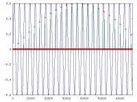
See below the most fine grain example for one of this process .
If there isn't a Cyclostationary process (the same as modulation) the samples
cant describing any sine wave out of 15khz by a linear law .
p.s. Sorry for my wrong english
Attachments
Last edited:
By this thread I m trying to know what happen to the signals on audio asynchronous acquisition
No you are not. It has been explained to you many times but you ignore and refuse to THINK. So your purpose here is not to learn but to troll.
Jan
Try fs/44100 signal (1Hz). 😀
How many envelopes do you see? 44100 or 44099? So?
Back to serious stuff.
I repeat: look at frequency spectrum!
AM Modulation has a spectrum shift and resize.

You loose the original signal. That signal is shifted in frequency (heterodyning) and resized in amplitude (due to cosine multiplying).
So if you apply a low pass filtering, you get nothing if F3 is below heterodynes.
If F3 overlap heterodynes, you get "something else", but NOT the original signal.
Sampling is quite different.
You've a spectrum repeat.
So you still have the original signal spectrum, only repeated for each Fs and, ideally, infinite times.
So you can get the original signal with a simple low-pass filter.
This is not due to cosine*cosine, as modulation is.
Sampling doesn't have any "*". It's another operator.
Just THINK about that.
Don't lauch simulations without understand basic math.
I repeat: get pencil and sheet. Write some basic formulas and go on.
Get a Signal Theory book, if helps.
Look at history too, if you like it...for example the old 1900's radio receivers, to understand the difference between sampling and modulation.
Be respectful of other's FACTS.
You won't believe?
Ok. Build a device.
For example, use a AM demodulator to extract original signal from a sampled one.
If you theory works, your device will work and you will get the analog signal.
SPOILER ALERT: it won't work. 🙂
How many envelopes do you see? 44100 or 44099? So?
Back to serious stuff.
I repeat: look at frequency spectrum!
AM Modulation has a spectrum shift and resize.
You loose the original signal. That signal is shifted in frequency (heterodyning) and resized in amplitude (due to cosine multiplying).
So if you apply a low pass filtering, you get nothing if F3 is below heterodynes.
If F3 overlap heterodynes, you get "something else", but NOT the original signal.
Sampling is quite different.
You've a spectrum repeat.
An externally hosted image should be here but it was not working when we last tested it.
So you still have the original signal spectrum, only repeated for each Fs and, ideally, infinite times.
So you can get the original signal with a simple low-pass filter.
This is not due to cosine*cosine, as modulation is.
Sampling doesn't have any "*". It's another operator.
Just THINK about that.
Don't lauch simulations without understand basic math.
I repeat: get pencil and sheet. Write some basic formulas and go on.
Get a Signal Theory book, if helps.
Look at history too, if you like it...for example the old 1900's radio receivers, to understand the difference between sampling and modulation.
Be respectful of other's FACTS.
You won't believe?
Ok. Build a device.
For example, use a AM demodulator to extract original signal from a sampled one.
If you theory works, your device will work and you will get the analog signal.
SPOILER ALERT: it won't work. 🙂
Last edited:
- Status
- Not open for further replies.
- Home
- Member Areas
- The Lounge
- Shannon ad fc/2 tricks