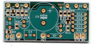
Looks OK at first glance, except for the 0V connection (PSU return ground) should be on the opposite side of the boards near the source resistor array 😉 edit: Remove the ground loop that runs around the board edges too..
Because all of the return current (2A) to the PSU runs through the 0V pad. You don't want to have this current running through your signal ground and mixing with the speaker return etc. In short, you will get higher distortion and noise. 😉
Member
Joined 2002
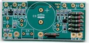
Mad_K said:Assembly completed. I think I'll take a break now and test them tomorrow 😉
WOAH! looks nice.. I love smd stuff. I should post a pic of what i just completed 🙂
When are we able to buy them from you ? When i purchase mine would you mind including the smd resistors and the smd transistors for a few extra $$
I just did a order for 20 resistors ( smd from mouser ) and well the resistors were 1$ us and the shipping was 12$ 🙁
JFet SEWA
Hi Mad!
Would it be possible to use paralleled JFets? I mean just to use 3 or 4 Lovoltech's Jfets instead of the one IRFP150.
Greets:
Tyimo
Hi Mad!
If you could find a JFET that can take as much heat as a MOSFET, you can simply pop it in the SEWA circuit with a minor adjustment of the bias voltage divider to account for the different VGS. However, since such a device is not yet avaliable, you'd have to get smart and utilize some tricks like cascode operation to get the dissipation down.
Would it be possible to use paralleled JFets? I mean just to use 3 or 4 Lovoltech's Jfets instead of the one IRFP150.
Greets:
Tyimo
Re: JFet SEWA
shure 😉
Tyimo said:Hi Mad!
Would it be possible to use paralleled JFets? I mean just to use 3 or 4 Lovoltech's Jfets instead of the one IRFP150.
Greets:
Tyimo
shure 😉
Looks pretty cool 😎
An IGBT would be the logic step forward in this construction, because of it's much more linear Vbs, compared to MOSFET.
An IGBT would be the logic step forward in this construction, because of it's much more linear Vbs, compared to MOSFET.
Thanks Lars, good suggestion. Unfortunately I don't have much time for developing new stuff novadays.
Now I'm drilling and tapping holes in my heatsinks 😉
(While listening to my brand new Gamma Ray - Majestic picture disc vinyl record) 😎
-Live The Music-
Now I'm drilling and tapping holes in my heatsinks 😉
(While listening to my brand new Gamma Ray - Majestic picture disc vinyl record) 😎
-Live The Music-
@mad_K
what potentiometer value suit for this amps ?
I have finish build this amps...
I will try ...
what potentiometer value suit for this amps ?
I have finish build this amps...
I will try ...
Re: JFet SEWA
i think you should pay more attention for input capacitance of lovotech jfet .
Tyimo said:Hi Mad!
Would it be possible to use paralleled JFets? I mean just to use 3 or 4 Lovoltech's Jfets instead of the one IRFP150.
Greets:
Tyimo
i think you should pay more attention for input capacitance of lovotech jfet .
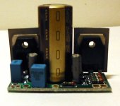
DC test: passed ;-)
The SEWA proto boards have passed the initial DC test.
There was a small change in idle current, because the BC850C only has a little over 0,5V BE drop in this circuit. Bias current dropped to 1,7A. This is a little on the low side for 4 ohm speakers, but might be beneficial for people with 8 ohm speakers and marginal heatsinks as the amp now only dissipats 38W pr channel. What do you think, should I change the idle current back up to 2A or alter the design to 1,7A idle current? (This is what I'll be using). I will be taking the AC signal and critical listening test tonight or tomorrow 😉
Member
Joined 2002
Re: DC test: passed ;-)
When should we pay for these Boards ? I guess ill have to build a buffer now to run this OR use the Bosoz Pre-Amp.
Mad_K said:The SEWA proto boards have passed the initial DC test.
There was a small change in idle current, because the BC850C only has a little over 0,5V BE drop in this circuit. Bias current dropped to 1,7A. This is a little on the low side for 4 ohm speakers, but might be beneficial for people with 8 ohm speakers and marginal heatsinks as the amp now only dissipats 38W pr channel. What do you think, should I change the idle current back up to 2A or alter the design to 1,7A idle current? (This is what I'll be using). I will be taking the AC signal and critical listening test tonight or tomorrow 😉
When should we pay for these Boards ? I guess ill have to build a buffer now to run this OR use the Bosoz Pre-Amp.
Thanks Mad!😀shure
i think you should pay more attention for input capacitance of lovotech jfet .
Yes, John!😉
Greets:
Tyimo
- Home
- Amplifiers
- Pass Labs
- SEWA - Seven Watt Amplifier