Oh PLEASE !!!!!!!!
Besides Country difference in puntuation, you do NOT repeat NOT use more than 1 (one) decimal separator (notice I don't call it either dot or comma because that is not the point).
Using just one decimal separator is the rule all over the World, no matter where.
After all, there is only one frontier between numbers >1 and <1 .
So, in notation most of the world is familiar with, it would look like 0.000,4%
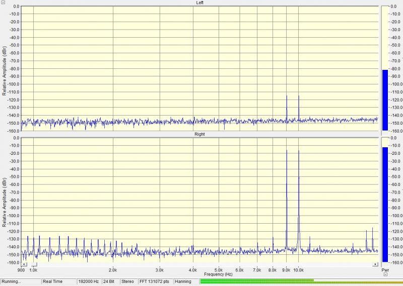
are both wrong, why do you insist?the level of distortions is about 0.000,15%, and 0.000.3%
Besides Country difference in puntuation, you do NOT repeat NOT use more than 1 (one) decimal separator (notice I don't call it either dot or comma because that is not the point).
Using just one decimal separator is the rule all over the World, no matter where.
After all, there is only one frontier between numbers >1 and <1 .
Well. Most importantly, we understood each other. 🙂
Additional separators between every three zeros we are allowed, I put them, not to be mistaken.
Additional separators between every three zeros we are allowed, I put them, not to be mistaken.
Last edited:
Oh PLEASE !!!!!!!!
are both wrong, why do you insist?
Besides Country difference in puntuation, you do NOT repeat NOT use more than 1 (one) decimal separator (notice I don't call it either dot or comma because that is not the point).
Using just one decimal separator is the rule all over the World, no matter where.
After all, there is only one frontier between numbers >1 and <1 .
Once again... ok, showing on a simple 1 million number:
1000000.00
1 000 000.00
1'000'000.00
1,000,000.00
all represent 1 million.
Same thing with less-than-one numbers.
In the UK we do not use separators after the decimal point.
The use of 1000 spearators is optional before the decimal point.
In a technical forum, we could avoid the problem of trying to read/write too many zeros by using parts per hundred (%), or parts per thousand (‰), or parts per million (PPM/ppm). Or we could use the dB ratio.
For simple number values (rather than ratios) we have the Internationally recognised multipliers.
Reading through that punctuation isn't a problem for me, although I like the PPM idea. 1ppm=0.0001%. Percent is not a very flexible unit here although it is common practice.
I wonder why the extra connection hasn't become popular for our amplifiers? What kind of wire do you typically use for it, is speaker wire sold in sets of 3 wires in Russia?
I wonder why the extra connection hasn't become popular for our amplifiers? What kind of wire do you typically use for it, is speaker wire sold in sets of 3 wires in Russia?
I don't know. You have a lot of smart people, but you have not mastered their minds, their development, their wealth.I wonder why the extra connection hasn't become popular for our amplifiers?
I have not seen the sale of speaker cables with three wires. But practical tests have shown that a regular copper speaker cable with a cross-sectional area of 6 mm square cut + one thin wire for information on the voltage drop at the "cold" wire gives the same sound, that of gold and silver, thick with good sausage, purchased abroad for big money.What kind of wire do you typically use for it, is speaker wire sold in sets of 3 wires in Russia?
The lesson is that thick silver with the gold cable has the same "natural" small resistance, and a relatively thin wire "artificially", with a special compensator resistance. But if sounds the same, why pay more? (C)
By the way, in one of the preamps from the Japanese company "Onkio" a canceller of interference induced in the cable between the units: a preamp and power amp.
It is also a loss to producers of expensive interconnect cables.
Op amps are the devil. I have achieved outstanding results with them, but I've found them to be unpredictable.
And I've read so much about THD, it's making me sick. What good is low THD if construction isn't any good, or if you have hum or noise on your output? I would spend less effort getting another -10 dB noise, and use that effort on construction, or at least, on power supply rejection on the schematic. To me this is far more important than THD. 0.1% THD can sound perfectly fine, provided it's due to 2 or 3 harmonics, each much lower than the previous one. And I believe odd harmonics sound good, it's the even ones and the higher ones that sound bad (there are plenty myths that 2nd harmonics don't sound bad, but in my experience this is false). 20 mVp-p (-40 dB) of supply noise on the output can ruin a listening room.
And I've read so much about THD, it's making me sick. What good is low THD if construction isn't any good, or if you have hum or noise on your output? I would spend less effort getting another -10 dB noise, and use that effort on construction, or at least, on power supply rejection on the schematic. To me this is far more important than THD. 0.1% THD can sound perfectly fine, provided it's due to 2 or 3 harmonics, each much lower than the previous one. And I believe odd harmonics sound good, it's the even ones and the higher ones that sound bad (there are plenty myths that 2nd harmonics don't sound bad, but in my experience this is false). 20 mVp-p (-40 dB) of supply noise on the output can ruin a listening room.
Last edited:
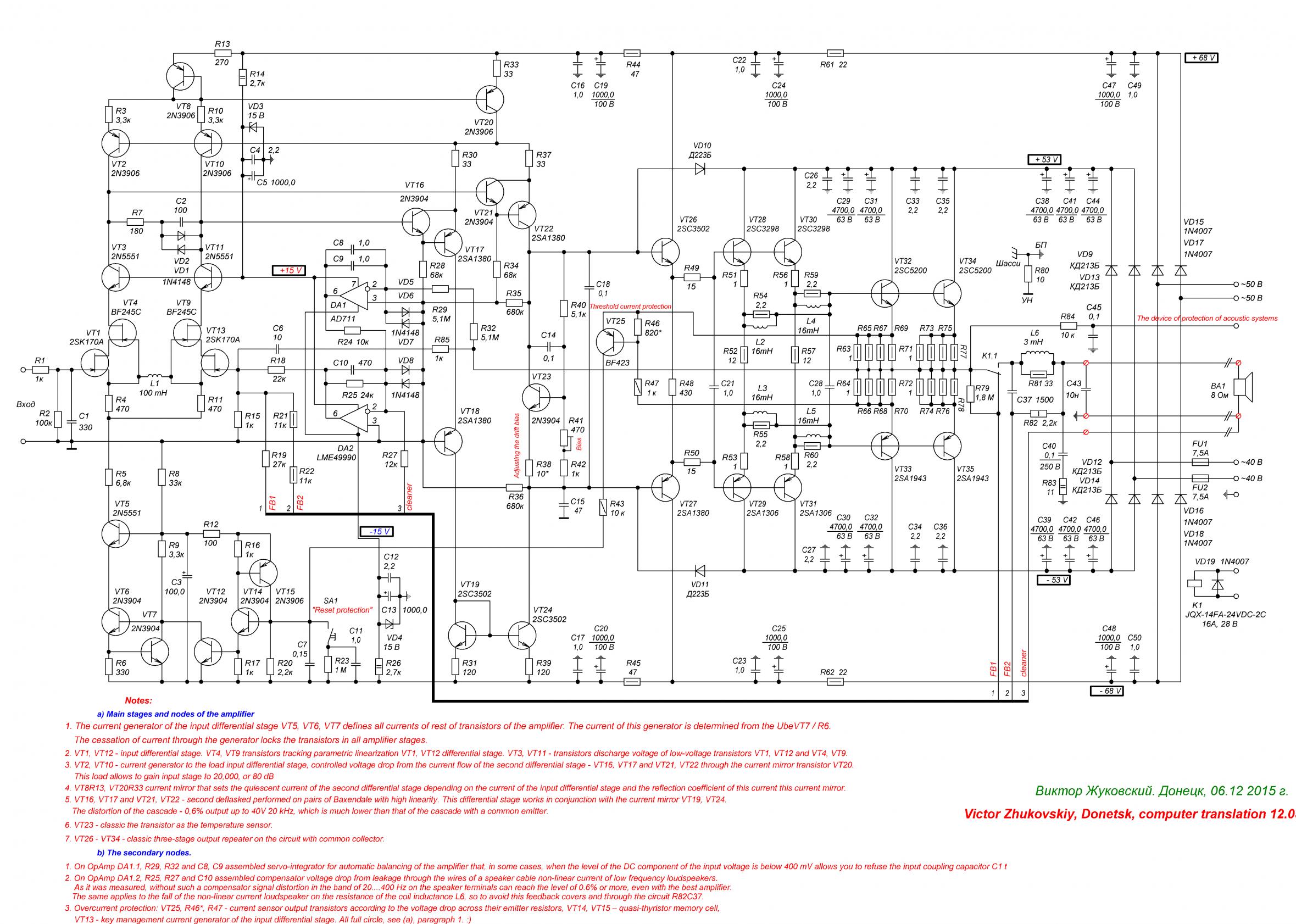
The amplifier in this diagram: http://www.diyaudio.com/forums/attachments/solid-state/548293d1462871663-several-schemes-2011.gif is simple and shows good results: http://www.diyaudio.com/forums/attachments/solid-state/548300d1462871663-several-schemes-19-20.jpg. For this circuit we built a lot of amplifiers. His diagram checked in LTSpice IV, all data of this program are confirmed - i.e., no unpredictability, a complete certainty. You can consider it for advertising: the engineers at Linear Technology was written by excellent software, they did a good job.Op amps are the devil. I have achieved outstanding results with them, but I've found them to be unpredictable.
I also read a lot about it and many were sick. 🙂 They why not just write, and it's very difficult and very scary. 🙂 Now I'm healthy, which I wish you. You can build good amps for little money, like us.And I've read so much about THD, it's making me sick.
The last thing worth caring about in these amplifiers, it is about noise at 1.5 volts input voltage. Such a large input voltage suppresses any conceivable noise. High linearity can be achieved by the selection circuitry, but hum - the consequences of poor amplifier design, for example, a failed mutual arrangement of the wires.What good is low THD if construction isn't any good, or if you have hum or noise on your output?
You don't have to sacrifice anything. Both issues solved here. For example, the scheme http://www.diyaudio.com/forums/attachments/solid-state/548293d1462871663-several-schemes-2011.gif has separate power supply VAS: +-68 volts, and the output stage: +-55 volts. Already this is enough to not worry more about power supply rejection, but, in addition, power supply VAS filtered circuits C51C53 R51C27C30 R43C14C17 it is just for one shoulder VAS.I would spend less effort getting another -10 dB noise, and use that effort on construction, or at least, on power supply rejection on the schematic. To me this is far more important than THD.
The output stage needs to have for proper management of heavy load, such as a WOOFER speaker, need a large amount of energy supply. Here the capacitance of the capacitor 47000 UF power and energy capacity of the capacitors of the power output stage 71 joule per channel, approximately 0.5 j per watt of output power.
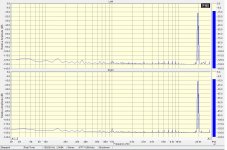
That's right, while we are talking about large distortions, for example, 50 ppm or 100 ppm. If the level of distortion on the noise level or below this level, is not so important the order of these harmonics and their relative value. It is important that we can't hear them. 🙂0.1% THD can sound perfectly fine, provided it's due to 2 or 3 harmonics, each much lower than the previous one. And I believe odd harmonics sound good, it's the even ones and the higher ones that sound bad (there are plenty myths that 2nd harmonics don't sound bad, but in my experience this is false). 20 mVp-p (-40 dB) of supply noise on the output can ruin a listening room.
Last edited:
It is important that we can't hear them. 🙂
That's it. If this is achieved, the amplifier is a success, complex or simple.
I use op amps, they're just not predictable. You can build a circuit to give you the illusion that they are, and in that circuit they may work as designed, but I still maintain they're unpredictable.
I have a design with which I have waged a war against distortion, but my original idea was to make an amplifier which has nice turn on and off characteristics. Anyway, the design is good. THD is very low, and I will build this one sometime. I've been working on the design for some time now. But I've let go of the THD war - it's good enough. I know I'll never hear it.
The amplifier in this diagram: http://www.diyaudio.com/forums/attac...hemes-2011.gif
tested with many types of OpAmp, even such as the ad8065 (with changes of frequency compensation circuits, of course), and all showed or fat the predictability and sustainability. I forgot with this diagram, what is generation or RF flash.
But there is diagrams and without the use of OU, such as this amplifier: http://www.diyaudio.com/forums/atta...1463048491-several-schemes-master-donetsk.jpg with these parameters: http://www.diyaudio.com/forums/attachments/solid-state/548676d1463048739-several-schemes-9_10-.jpg here http://www.diyaudio.com/forums/solid-state/290970-several-schemes.html. This amp is better, than the previous, but as they say, it is more difficult.
Op amps are the devil.
We can perform an exorcism for little money. 🙂
http://www.diyaudio.com/forums/solid-state/290970-several-schemes.html#post4711094
OPAMP introduces much less distortion in schemes such as discussed than in the cascades with a single OPAMP.
One of the main factors of distortion in OPAMP is a differential input voltage. With one OPAMP in the output voltage of 2 V, a frequency of 20 kHz and the OPAMP gain of 60 dB (60 dB for a good OPAMP to the frequency of the input differential voltage of 2 millivolts. In the discussion of the amplifier after the OPAMP installed cascades with a gain of 250 (48 dB). Therefore, despite much more PowerAmp output voltage (40 V), the OpAmp operates with an input differential voltage signal is about 250 microvolts, and the input stage introduces much less distortion than a single OpAmp.
The second factor of distortion is the magnitude of the output voltage of the OPAMP. If one OPAMP is forced to give 2 Volt here the output voltage the output voltage of the OPAMP does not exceed 250 mV at a frequency of 20 kHz at rated output power of the amplifier, and decreasing of output power and signal frequency the output voltage of the OPAMP is reduced, together with him and reduced distortion.
The third factor of distortion is the load impedance OpAmp. The smaller the load resistance of OpAmp, the less distortion it introduces. Single OpAmp without buffer cascades runs on load of a few kilo Ohm, which includes the forced low resistance of the feedback loops. While discussing the amplifier OpAmp load is about 100 kilo Ohm.
On all three factors of the distortion of this OpAmp operates in the small-signal regime, in the conditions of Paradise. So it makes vanishingly low distortion.
The smaller the load resistance of OpAmp, the less distortion it introduces. Single OpAmp without buffer cascades runs on load of .
This is not so, in most OPAMP distortion goes up with smaller load resistance.
Probably you meant, smaller load(higher load resistance) less distortion.
Probably you meant, smaller load(higher load resistance) less distortion.
Yeah, didn't read the translation. Exactly as you said.
If single OpAmp is loaded on a few kilo Ohm, here http://www.diyaudio.com/forums/attachments/solid-state/548293d1462871663-several-schemes-2011.gif the OpAmp DA1 load is about 100 kilo Ohm.
We can perform an exorcism for little money. 🙂
OPAMP introduces much less distortion in schemes such as discussed than in the cascades with a single OPAMP.
Op amps can give good results, and can be very convenient. I'm not afraid to use them, my last design has one:
Simple preamp
It's only used as an inverter, and now a filter, and the preamplifier there isn't the best quality, but it does the job. In the past I have had oscillations caused by the op amps. I have learned how to stop that, but still.
Some OpAmps are internally corrected for using then as a unity gain buffer as-is with no issues, some others - are not. It's normally stated in a datasheet.
Example - Burr-Brown OPA-627. It's expensive but excellent for audio and corrected properly by design.
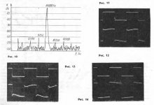
I found a few drawings illustrating the operation of the compensator resistance of the wires of the speakers. This is the waveform of the transient characteristics at the terminals of speakers: Fig. 12 - the resistance of the speakers 8 Ohm, Fig. 13 - when the resistance is 4 Ohms, the pulse repetition frequency of 50 Hz, above - input, below - the loudspeaker terminals.
The load used speakers "Technics" SB-3170 8 Ohms, to get 4 ohms connected in parallel.
On the fronts of the signal bursts are visible - the consequences of voltage of self-inductance of the speakers. In normal conditions without compensator, these spikes degrade the damping of woofers and midrange speakers reproduce them.
In Fig. 14 shows the transient response enabled by the compensation device. We see a complete disappearance of the bursts of self-inductance of the woofers.
Attachments
The device soft-start and protection of acoustic systems with printed circuit board. Designed for these amps.
http://www.diyaudio.com/forums/atta...ce-soft-start-protection-acoustic-systems.gif
http://www.diyaudio.com/forums/atta...ce-soft-start-protection-acoustic-systems.gif
http://www.diyaudio.com/forums/atta...ce-soft-start-protection-acoustic-systems.gif
http://www.diyaudio.com/forums/atta...ce-soft-start-protection-acoustic-systems.gif
Amplifier circuit for headphones.
Attachments
There was at least one speaker company that used a "third wire" to feedback from the speaker terminals. This was in the 1970s in the USA. I can not right now recall the name of the company, but they still have a following.
They also used the wire to do EQ on the bass at the same time.
It's not a new idea, fyi.
_-_-bear
They also used the wire to do EQ on the bass at the same time.
It's not a new idea, fyi.
_-_-bear
- Status
- Not open for further replies.
- Home
- Amplifiers
- Solid State
- Several schemes