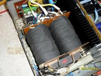
Without any words - something like that.
Attachments
Last edited:


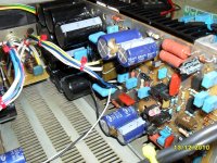
Like so...
Attachments

OK, some topology fragments are rather interesting, although known to me.
I tend not to use OpAmps in the signal path due to many reasons (only as a servo).
Are those your designs?
I tend not to use OpAmps in the signal path due to many reasons (only as a servo).
Are those your designs?
Yes, this is my design.
What exactly don't like OpAmp in power amplifiers, Вася Зайченко?
I'm Valery (ok, never mind).
Well, it's rather subjective... I mean - it's possible to design a good amplifier with an OpAms as well as without an OpAmp (as well as the bad one 😉), however I prefer having more "control", seeing what exactly is happening in every bit of the power amp.
I like OpAmps in the line stages or some "instrumental" converters though.
Still using a multi-channel subsonic filter in one of my systems, built on Burr-Brown OPA627 chips - it just "does not sound", like it's not there. Full transparency 😎
I ave PM-ed you my email, by the way.
Cheers,
Valery
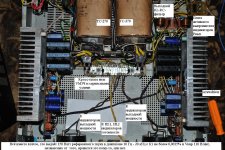
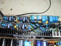
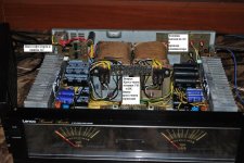
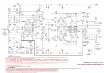
In my opinion, "Sansui" too complex and expensive. You can gather simple amplifier, with the best parameters. For example here is a schematic diagram of a powerful amplifier, harvested in the amount of several copies.
Attachments

Last edited:
My opinion with regards to MOSFETs - you just have to drive them the right way, especially the HexFETs. OK, yes - they've got the high, non-linear input capacitance - so what? If you drive them with low-impedance emitter follower - not really a problem. On the other hand, they are cheap and very reliable.
See one of my designs here: CF-FET V2.0
A high-speed amp with the right use of HexFETs. The OPS was initially designed by Ostripper with BJTs at the output, later on I have "adapted" it for HexFETs. One of the amplifiers I like a lot.
Lateral FETs are different creatures, but also very good for audio.
By the way, Sansui-inspired design: TubSuMo tube hybrid
Version with BJTs at the input: BipSuMo with BC546B
Measurements with both Lateral FETs and BJT-based NS-OPS (non-switching) are in the next post there.
Sorry! 🙁I'm Valery (ok, never mind).
OPAMP introduces much less distortion in schemes such as discussed than in the cascades with a single OPAMP.Well, it's rather subjective... I mean - it's possible to design a good amplifier with an OpAms as well as without an OpAmp (as well as the bad one 😉), however I prefer having more "control", seeing what exactly is happening in every bit of the power amp.
I like OpAmps in the line stages or some "instrumental" converters though.
Still using a multi-channel subsonic filter in one of my systems, built on Burr-Brown OPA627 chips - it just "does not sound", like it's not there. Full transparency 😎
I ave PM-ed you my email, by the way.
Cheers,
Valery
One of the main factors of distortion in OPAMP is a differential input voltage. With one OPAMP in the output voltage of 2 V, a frequency of 20 kHz and the OPAMP gain of 60 dB (60 dB for a good OPAMP to the frequency of the input differential voltage of 2 millivolts. In the discussion of the amplifier after the OPAMP installed cascades with a gain of 250 (48 dB). Therefore, despite much more PowerAmp output voltage (40 V), the OpAmp operates with an input differential voltage signal is about 250 microvolts, and the input stage introduces much less distortion than a single OpAmp.
The second factor of distortion is the magnitude of the output voltage of the OPAMP. If one OPAMP is forced to give 2 Volt here the output voltage the output voltage of the OPAMP does not exceed 250 mV at a frequency of 20 kHz at rated output power of the amplifier, and decreasing of output power and signal frequency the output voltage of the OPAMP is reduced, together with him and reduced distortion.
The third factor of distortion is the load impedance OpAmp. The smaller the load resistance of OpAmp, the less distortion it introduces. Single OpAmp without buffer cascades runs on load of a few kilo Ohm, which includes the forced low resistance of the feedback loops. While discussing the amplifier OpAmp load is about 100 kilo Ohm.
On all three factors of the distortion of this OpAmp operates in the small-signal regime, in the conditions of Paradise. So it makes vanishingly low distortion.
Last edited:
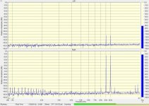
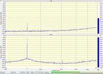
20KHz - 0.032% (measured at 50W @ 8 ohm (с) audio | Project CF-FET V2.0My opinion with regards to MOSFETs - you just have to drive them the right way, especially the HexFETs. OK, yes - they've got the high, non-linear input capacitance - so what? If you drive them with low-impedance emitter follower - not really a problem. On the other hand, they are cheap and very reliable.
See one of my designs here: CF-FET V2.0
A high-speed amp with the right use of HexFETs. The OPS was initially designed by Ostripper with BJTs at the output, later on I have "adapted" it for HexFETs. One of the amplifiers I like a lot.
Lateral FETs are different creatures, but also very good for audio.
By the way, Sansui-inspired design: TubSuMo tube hybrid
Version with BJTs at the input: BipSuMo with BC546B
Measurements with both Lateral FETs and BJT-based NS-OPS (non-switching) are in the next post there.
Is this really serious? We live in the twenty-first century, not the 70-ies, it is a shame to build amplifiers with distortion more than 0.001%.
20KHz - 0.032% (measured at 50W @ 8 ohm (с) audio | Project CF-FET V2.0
Is this really serious? We live in the twenty-first century, not the 70-ies, it is a shame to build amplifiers with distortion more than 0.001%.
Well, THD number does not mean anything by itself. It's always possible to design an amplifier with extremely low THD on purpose. See this one here for example - Vertical CFA. But... there's no such purpose 😉
It a proper blind A/B listening test of 2 good amplifiers, showing 0.05% and 0.00005% THD, measured on a sine wave, you will most likely not distinguish a difference because of THD difference. Most likely you will like or not like the sound because of some other reasons.
Later on, I have designed a VFA version of Vertical with 2 feedback loops, having much less feedback loop gain around the output stage - and higher distortion and lowed damping factor, but I like its sound better with my speakers, especially in the bass area.
CF-FET V2.0 has got higher distortion, but much higher slew rate (around 250V/uS) at the same time. Which one is better? Depends on the listeners taste.
Sorry, can't bring myself to believe in so much high indicators in this schematic audio | Project VERTICAL audio | Project NS-OPS. Yesterday I tried to squeeze something from a much more sophisticated CFA circuit, but attempts to squeeze at least 0,000.4% failed. A real amplifier will make more of a distortion than an idealized model.
Quote:
"Theory is, when you know everything – and nothing functions.
Practice is, when everything works, but nobody knows why.
At our place theory and practice are united in beauty:
Nothing functions and nobody knows why."
I have been doing audio for nearly 50 years and I have yet to seen a really good relation between perceived sound and the measurements.
Kind regards Vitreus
PS. I don't like opamps either and I have lot of reasons, but I don´t know if they are relevant.
Sorry, can't bring myself to believe in so much high indicators in this schematic audio | Project VERTICAL audio | Project NS-OPS. Yesterday I tried to squeeze something from a much more sophisticated CFA circuit, but attempts to squeeze at least 0,000.4% failed. A real amplifier will make more of a distortion than an idealized model.
Level of sophistication also does not mean anything by itself 😉
The right topology solutions - yes, they matter.
Those are the real measurements I can reproduce any time.
But again - VFA option with double-loop feedback and much higher THD - I like the sound even better.
I have been doing audio for nearly 50 years and I have yet to seen a really good relation between perceived sound and the measurements.
Kind regards Vitreus
PS. I don't like opamps either and I have lot of reasons, but I don´t know if they are relevant.
Yes, here our views differ. You can see that different people like different sound, but, usually, comprehensive improvement of the measured parameters as felt by the majority of the sound improvement. The sounds do not interfere with the music.
Nowadays OpAmp is used everywhere, it is difficult to build an amplifier on lamps and to avoid the use of multiple monolithic DAC with OpAmp as a sound source. Also before getting into the DAC the sound has passed through several OpAmp in the sound consoles of Directors.
The best regards.
The speed and comfort of the Mercedes is higher than the scooter.😉Level of sophistication also does not mean anything by itself 😉
But again - VFA option with double-loop feedback and much higher THD - I like the sound even better.
Double loop feedback is contrary to the achievement of high linearity themes. due to its application falls depth feedback and growing differential input voltage - a factor of increasing distortion. It can be good to see on the model.
especialy when Mercedes stands still in a traffic jam and the scooter rides on cheaply🙄The speed and comfort of the Mercedes is higher than the scooter.😉
TDouble loop feedback is contrary to the achievement of high linearity themes...
this ia all about...
for me Vzaichenko got right, THD alone gives nothing and for many listeners -60dB from fundamental is more than enough

however I appreciate your contribution in pushing diy audio forward🙂
The speed and comfort of the Mercedes is higher than the scooter.😉
Double loop feedback is contrary to the achievement of high linearity themes. due to its application falls depth feedback and growing differential input voltage - a factor of increasing distortion. It can be good to see on the model.
High-gain global NFB loop is not the only way of achieving high linearity. And not the best one. A good point for discussion.
especialy when Mercedes stands still in a traffic jam and the scooter rides on cheaply🙄
That's good.this ia all about...
for me Vzaichenko got right, THD alone gives nothing and for many listeners -60dB from fundamental is more than enough
however I appreciate your contribution in pushing diy audio forward🙂
Let everyone builds what he can do, and listens to what happened. Amen (it's a religious war, isn't it?) 🙂
Best regard.
Last edited:
- Status
- Not open for further replies.
- Home
- Amplifiers
- Solid State
- Several schemes