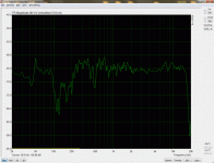
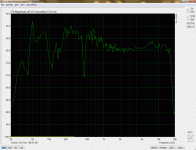
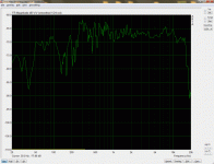
For setting up multiple subs we want to look at the frequency response in real time. Here's a comparison of two different analyzers:
SignalScope Pro
Pink Noise on Octave Band Analyzer:
White Noise on Octave Band Analyzer:
Pink Noise on Real Time FFT Analyzer:
White Noise on Real Time FFT Analyzer:
Pink/White Noise with REW5
SignalScope Pro
Pink Noise on Octave Band Analyzer:
An externally hosted image should be here but it was not working when we last tested it.
White Noise on Octave Band Analyzer:
An externally hosted image should be here but it was not working when we last tested it.
Pink Noise on Real Time FFT Analyzer:
An externally hosted image should be here but it was not working when we last tested it.
White Noise on Real Time FFT Analyzer:
An externally hosted image should be here but it was not working when we last tested it.
Pink/White Noise with REW5
An externally hosted image should be here but it was not working when we last tested it.
An externally hosted image should be here but it was not working when we last tested it.
An externally hosted image should be here but it was not working when we last tested it.
An externally hosted image should be here but it was not working when we last tested it.
Ah, thanks Markus those examples helped. Using my tools I can set a linear frequency axis ( the data points, not the chart scaling) to achieve a flat plot with white noise.
The use of white versus pink depends on the filter type in the analyzer. FFT's are constant bandwidth filters and white noise will have a flat spectrum. When any type of averaging based on "octaves" is used then the effective filters are constant % bandwidth and the actual bandwidth increases with frequency. In this case the excitation must fall by "octaves" or -3 dB / oct. which is pink noise.
Pink is also less hazardous to HF units during high power testing.
And low pass filtered even less 🙂
I used the sample available on Markus' website. It is band limited to 400Hz.
I assumed this 60 second file was made up of repeated loops, as this naturally would have an effect on how fast I could sweep the mic. The testing went well.
I bought an equaliser and tweaked the bass into line and although it is still quite peaky, my listening impression is that my room is no good. It is 24x12x9 but it opens up into three other rooms and these openings are not symmetrically placed. The walls are lossy and I have moderate bass trapping.
Should setting up multi subs be any harder for me than if I had a dedicated sealed room?
Should setting up multi subs be any harder for me than if I had a dedicated sealed room?
Lets just say "maybe yes, maybe no." There is no fixed situation as every room is different. I see lots of rooms and no two have the same problems even though there are certainly a set of very common situations.
The bottom line is that if you can get the LF response smooth with a shallow rise towards DC then this is "ideal". But don't confuse objective and subjective. They may not be the same. While most people raise the subjective as the ideal, I raise the objective as the ideal. Then after living with this objective ideal for awile I come to find that it is always the best choice although that isn't always the case initially. Let the data train your ears, not the other way arround.
Let the data train your ears, not the other way arround.
Sounds right, feels wrong, but sounds fair. Then, I have used measurements to convince myself of things before, but since setting up based purely on power response measurements, some recordings sound warm, some cold, some dull, some bright....the median timbre of all recordings has been close to ideal....so I certainly have some reservations about using some random recording for critical listening, in fact now when I hear a speaker that sounds similar on all recordings, I know something about that set up.
I am now going to turn my speakers a further 10 degrees off axis because I suspect that the listening axis response should resemble the power response.
I'm also going to hang some new first reflection absorbers. I'm hoping 2 inch rockwool spaced at 4 inches with a 30 degree incidence will damp a 200Hz cancellation that is already 12dB down from the direct sound.
some recordings sound warm, some cold, some dull, some bright
You have to know the recording being used for any subjective tests. Otherwise you could be evaluating the recording when you think that you are evaluating the sound system.
When someone comes over to hear my system, I know right away by what they bring (or nothing) how serious a listener they are. One guy came with no source material at all, and guess what he wasn't serious at all.
This is such a great step from the old days where my sound would have some bad characteristic in all but 10 percent of the material.
I am currently trying to track down a sharp null at 410Hz on listening axis at 1m, and I have tested adding a temporary 4 inch rockwool absorber at each reflection point and each cabinet boundary. For all I know it may be a room mode. Is there a step by step process I can go through to find it?
I am currently trying to track down a sharp null at 410Hz on listening axis at 1m, and I have tested adding a temporary 4 inch rockwool absorber at each reflection point and each cabinet boundary. For all I know it may be a room mode. Is there a step by step process I can go through to find it?
A sharp null at 410Hz? How wide? That's probably more of a visual problem when looking at graphs than an audible problem.

Here it is.
Is this a steady-state response? All speakers playing?
Does the dip go away when you measure to the left and the right? Does the other speaker have the same dip?
Looks like a pronounced boundary interference. Moving the speakers and/or listening location should help.
Moving right back changes it all. If it was destructive interference, I guess I should have known by the 'shoulders' of the null indicating constructive interference either side.
If it's a boundary issue, this can help you find it: http://www.htguide.com/forum/attachment.php4?attachmentid=18177
- Status
- Not open for further replies.
- Home
- Loudspeakers
- Multi-Way
- Setting up the Nathan 10