km processor pr2
my english is very bad, y have tried to open a black box of processor KM PR2, but i have lost the values of resistors and capacitors.
Have you establish a schema of the circuit pro 05 and the black box so5
best regards
Hello,
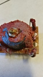
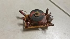
I'm talking about the one that is the pre-amplifier ( see attached fotos) BUT my description will help you to find out what is in any blackbox ( servo sound , KM )
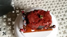
Detail : the blackbox is just plastic and is surrounding the epoxy.
If you squeeze the plastic , it comes off, and shows you a brown epoxy box.
Also interesting : on the KM-52 speaker , there is no blackbox on the double-sided pcb !!
my english is very bad, y have tried to open a black box of processor KM PR2, but i have lost the values of resistors and capacitors.
Have you establish a schema of the circuit pro 05 and the black box so5
best regards
blackbox preamplifier PR2 and PR6
Patent FR_2208155_A1-1.pdf is describing the idea what is inside the blackbox of the PR2 , PR6 pre-amplifier ( KM )
Compared blackboxes , some differences exist
Attached schematic of the servo-sound 15b amplifier
Whats next ?
Patent FR_2208155_A1-1.pdf is describing the idea what is inside the blackbox of the PR2 , PR6 pre-amplifier ( KM )
Compared blackboxes , some differences exist
Attached schematic of the servo-sound 15b amplifier
Whats next ?
Attachments
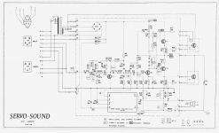
Can somenody explain that circuit to me. It is drawn for maximum impenetrability - not to mention the crucial board that is blank.
B.
B.
servo-sound SL70 pre-amplifier
Hello,
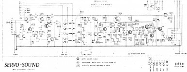
In attachment you can find the schematic of the pre-amplifier.
T1 and T2 = RIAA amplifier , output 100mV
All line levels (100mV) .
Between T2 and T3 we find a lattice network (stereo crossing) that is described in patent US3659217
Due to this network , the 100mV line level is attenuated to 30mV.
This weak 30mV signal is then appied to T3
After T3 we find tone controle circuit with P1(10K) and P2(10K) bass , treble
P3(10K) : logically balance control
P4(10K) : volume control with RC equal loudness compensation network
Output of T4 = 30mV ?
250mV signal level goes to T5
T6 final amplifier stage , output signal 250mV
Signal coupling capacitors : phono : C1 and C7 = 2,2µF
line level : C15, C22, C24, C27, C29, C30
All transistors BC154
Power supply comes from speaker , RC filters : R45+C31 , R45+C17, R12+C6,
Power supply for phono : double RC filter : R12+C6 and R5+C3
Regards,
Peter
Hello,
In attachment you can find the schematic of the pre-amplifier.
T1 and T2 = RIAA amplifier , output 100mV
All line levels (100mV) .
Between T2 and T3 we find a lattice network (stereo crossing) that is described in patent US3659217
Due to this network , the 100mV line level is attenuated to 30mV.
This weak 30mV signal is then appied to T3
After T3 we find tone controle circuit with P1(10K) and P2(10K) bass , treble
P3(10K) : logically balance control
P4(10K) : volume control with RC equal loudness compensation network
Output of T4 = 30mV ?
250mV signal level goes to T5
T6 final amplifier stage , output signal 250mV
Signal coupling capacitors : phono : C1 and C7 = 2,2µF
line level : C15, C22, C24, C27, C29, C30
All transistors BC154
Power supply comes from speaker , RC filters : R45+C31 , R45+C17, R12+C6,
Power supply for phono : double RC filter : R12+C6 and R5+C3
Regards,
Peter
Attachments
Hello everybody,
First of all best whishes for 2017.
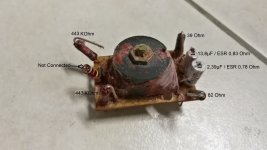
I finally finished dismantling the blackbox of the PR2-2 preamplifier.
I measured all the values .
Since I got expierenced in dismantling 2 blackboxes of preamplifiers I could now start with the blackbox inside de servo-sound speaker, pcb type 15b .....
if you folks are still interested ?
Regards,
Peter
First of all best whishes for 2017.
I finally finished dismantling the blackbox of the PR2-2 preamplifier.
I measured all the values .
Since I got expierenced in dismantling 2 blackboxes of preamplifiers I could now start with the blackbox inside de servo-sound speaker, pcb type 15b .....
if you folks are still interested ?
Regards,
Peter
Attachments

- Status
- Not open for further replies.