There is of course pros and cons with accelerometer feedback.
Fiddling and removing dustcap could be hard if you are not steady on your hand.
But when it´s properly and stiff installed....
Granted, I still think back-EMF current feedback is quick yet quite good as an approach..... but another issue with accelerometers reported here a few times is stiffness of the mounting substrate of the device, as you say. We're correcting really tiny motions and any motion of the sensor even if imperceptible to human fingers hurts.
B.
No, it is not the same - it is a measuring system. Read how to measure the driver impedance vs frequency with the voltage and current arm:The voltage sensing circuit is the same as in every low output impedance audio amp in the entire known universe (as far as I can understand his inspirational picture). It is feedback that corrects the amp (and not incidentally, to render the amp a low output impedance source of power). It doesn't sense anything about the driver.
See the diagram on page 11:
http://www.audiomatica.com/wp/wp-content/uploads/APPNOTE_011.pdf
Also the diagrams on page 5:
http://www.artalabs.hr/AppNotes/LIMP_Tutorial_Version_2_4_English.pdf
Please stop insulting professor Klippel... and all educated engineers.Klippel's diagram - and other stuff of his I've read - is much distorted by commercial motivation and the need to fool the patent office into thinking you are innovative. But Klippel doesn't blush as much.
I think your personal insults are out of place here. Please stop it.
Please see and hear how the Klippel system eradicates driver nonlinear distortion:
YouTube
YouTube
(sound is on at approx 0:45)
Last edited:
No, it is not the same - it is a measuring system.
Well, in the end it is just a voltage measurement and a current measurement. There is nothing special about that.
The real special part is what Klippel does with the fed back current and voltage.
Maybe a (re)read of the papers published by Rob. Your first sentence clearly states that you missed something...
I meant things like grill rattle, cone slap (both super annoying but unrelated to MFB) and mechanical limit effects not a gradual increase in harmonic distortion with output increase. Effects such as the suspension suddenly becoming too tight to prevent further movement or the coil totally leaving the gap can't be corrected by feedback. Furthermore they could cause loop instability which would result in more noise due to the feedback. With this in mind I am also of the opinion that a MFB system has to be turnkey because limiting is needed to avoid these effects.
I meant things like grill rattle, cone slap (both super annoying but unrelated to MFB) and mechanical limit effects not a gradual increase in harmonic distortion with output increase. Effects such as the suspension suddenly becoming too tight to prevent further movement or the coil totally leaving the gap can't be corrected by feedback. Furthermore they could cause loop instability which would result in more noise due to the feedback. With this in mind I am also of the opinion that a MFB system has to be turnkey because limiting is needed to avoid these effects.
These are some clever remarks you make! Yes, limiting is compulsary to prevent the feedback loop over correcting the mechanical limits of a driver. To keep it simpel: when the system reaches the limits of a driver, it will try to correct it with more power. In the end the amp will clip and the train will derail. In our design we use a failsafe, there is a crude limiter driven by the clip output from the hypex amp module and will lower the level in the feedback loop with 30-40db. This is very audiable so we also use a pre limiter.
You could detect over excursion of the driver by a change in the apparent inductance of the voice coil as it goes out of the gap (I think some void amplifiers (inf 8?)) had a system to detect this. I'm also aware of some people using optical excursion limiting (for which the sensors are expensive to do in real time). I had some success using cheap sharp IR sensors to do excursion measurements on a driver that could be used to characterize a drivers real world excursion limitations:
measuring excursion - Bass Gear - Data-Bass Forums
have you experimented with attempting to linearize the driver without feedback before you apply feedback?
measuring excursion - Bass Gear - Data-Bass Forums
have you experimented with attempting to linearize the driver without feedback before you apply feedback?
I see no reason what so ever to drive the transducer to the limit where the voice coil is leaving the gap.
Maybe in single occasions on a transient, but at those cases i only see acceleration feedback as a solution. And once again, if you have several subs (mono) it´s enough to have one acceleration sensor on one sub and then let all the subs be driven by the same corrected signal.
Maybe in single occasions on a transient, but at those cases i only see acceleration feedback as a solution. And once again, if you have several subs (mono) it´s enough to have one acceleration sensor on one sub and then let all the subs be driven by the same corrected signal.
That is exactly what I said, wondering why bentoronto can not see that measuring simultaneously voltage and current gives the woofer impedance vs frequency in the real time.Well, in the end it is just a voltage measurement and a current measurement. There is nothing special about that.
That is exactly what I said, wondering why bentoronto can not see that measuring simultaneously voltage and current gives the woofer impedance vs frequency in the real time.
First of all, naming it "voltage" or "current" is somewhat arbitrary. These audio amps control "voltage"; the feedback signal called "current" (across the small-value resistor) is simply the voltage across that resistor which is acting as a voltage divider with the driver. That signal relates to the driver impedance since the voltage is constant (and/or is an accessible variable when music is playing) and only the driver is varying.
The labeled "voltage" feedback at the output of the amp only serves to make the amp correspond to whatever signal was present at the input. As I tried to explain before, the effect of this "voltage" loop in ordinary audio amps is to make the signal flat and to IGNORE the variations in impedance of the speaker as it plays. That is not motional feedback: it is the opposite.
In rational practice, the amp "voltage" loop is inside the motional feedback loop. And I don't think you can't have loops intersect, as Kiippel's inspirational diagram might suggest, if I understood it.
The voltage loop makes the amp low output impedance. The motional feedback loop by current sensing (back-EMF) makes the amp a negative output impedance source - no kidding (and remarkable to measure it when your system is running). I suspect that is true of accelerometer sensing and hope somebody can post about it.
B.
This is a huge improvement in your thinking, regarding your previous post...the feedback signal called "current" (across the small-value resistor) is simply the voltage across that resistor which is acting as a voltage divider with the driver. That signal relates to the driver impedance...
which was outrageously wrong.It doesn't sense anything about the driver.
So, can we now finally agree on such a simple concept that current sensing (via small resistor) plus voltage sensing together make an impedance measuring system (Ohm law: z=u/i)?
Nope, according to your wrong reasoning that the voltage sensing signal must be separate from the current sensing one:
Why is so difficult for you to understand that the Clippel Controlled Sound system is measuring the driver impedance (z=u/i in the real time), then converting it to the woofer parameters - as an input in the Audio Signal Processing unit? The other input in the Processing unit is an incoming audio signal (from some audio source). Output of the Audio Signal Processing unit then is fed into an ordinary audio amplifier, which has his own (voltage) negative feedback loop for decreasing amp output impedance (and amp distortion).the effect of this "voltage" loop in ordinary audio amps is to make the signal flat and to IGNORE the variations in impedance of the speaker as it plays...
The voltage loop makes the amp low output impedance. The motional feedback loop by current sensing (back-EMF) makes the amp a negative output impedance source
Last edited:
It is working - see the measurement and hear the recorded sound in the videos here:And why is this still not working after 25 years in a commercial product?
KLIPPEL CONTROLLED SOUND
The Clippel system is not 25 years old, it is brand new. Maybe it will hit the market sooner than the expected Hypex Motional Feedback amplifier, I don't know.
I have asked the moderators to have a few private words with you about your unremitting abuse.It is working - see the measurement and hear the recorded sound in the videos here:
KLIPPEL CONTROLLED SOUND
The Clippel system is not 25 years old, it is brand new. Maybe it will hit the market sooner than the expected Hypex...
In the link, the Klippel man repeatedly says, "current" sensing. Strange to propose a video on my laptop being used as proof of great audio by Klippel!
While impedance is an interesting parameter, the only parameters of interest for feedback are those that reflect the motion of the cone or sound output. Most of the T/S parameters don't qualify, or at least, "the news hasn't come to Harvard" as the old song goes. The good old current MFB senses back-EMF, which I believe I may have mentioned previously, does reflect cone motion well enough to greatly impress anybody who has tried it.
(As I speculated earlier, it is possible that a sophisticated and empirical model of a driver can be usefully wired-in somewhere for SQ or protection. The benefits don't seem like much to me although the patent office might be ga-ga.)
What's really interesting - for those who have watched the commercialization and patenting of MFB over the decades (and here I include Philips) - is that once again the exhaulted Klippel Corp is striving to once again "make a silk purse out of a sow's ear". In the link Sonce provided, the dramatic example is a very small speaker meant for cars. It makes the bass a lot better. I'll keep that in mind if I want a loud stereo in my car or motorcycle.
Since all you need is a simple current sensing resistor, this approach is ideal for cellphones too. (Betcha Klippel Corp has sniffed that in the wind too.)
So once again, this is stuff meant to impress the patent office but - as far as I can tell just now - of no great relevance to the audiophiles at DIYaudio who start with great woofers and want to make them better.
B.
Last edited:
I suppose you are referring to the first video for automotive sound:In the link Sonce provided, the dramatic example is a very small speaker meant for cars. It makes the bass a lot better. I'll keep that in mind if I want a loud stereo in my car or motorcycle.
YouTube
Above example is simply a proof of the concept - if it works for a small speaker, it will work for a big one also. And it works - even you admit that!
I recommended other two videos before, in the next section CANCELLATION OF NONLINEAR DISTORTION. The first video is with bigger 6-inch woofer (not for car):
YouTube
Keep that in mind if you want a loud, low distortion stereo with big hi-fi woofers in your home. Also for pro use.
Last edited:
 Please steer clear of personal remarks and insults. Those are not allowed on this forum. Failure to follow the rules will find you in read only mode.
Thanks for the link.
Servo subwoofers vs Ordinary subwoofers
In theory, servo controlled subwoofers should be much better than ordinary subwoofers. But, real life is somewhat different. Data-Bass site ( dB v2 ) tested many subwoofers in great detail, including Servo controlled subwoofers. How they compare to an ordinary, plain vanilla subwoofer? I made a simple chart with the data from Data-Bass tests. Rythmik and Velodine models are well regarded Servo controled subwoofers with 18" drivers (Rythmik FV25HP has two 15" drivers). Ordinary, passive subwoofer is with 18" pro woofer BMS 18N862. All THD measurements were made at SPL=115 dB.
Here are the results (on the left side is THD percentage). Surprise, surprise!
Attachments

Last edited:
Well the BMS woofer is setting you back 550 USD for the driver only.
Put a servo on the BMS and you get 10dB reduction easy and very low cost..
Put a servo on the BMS and you get 10dB reduction easy and very low cost..
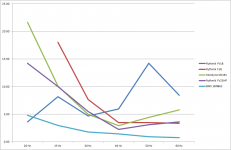
You are missing the point: the most revered Servo controlled subwoofers are much worse than an ordinary pro woofer slapped in a vented box!Well the BMS woofer is setting you back 550 USD for the driver only. Put a servo on the BMS and you get 10dB reduction easy and very low cost..
"Very low cost"?? Let see:
Rythmik FV18 = $1874
Rythmik F18 = $1630
Velodyne DD18+ = $5000
Rythmik FV25HP = $2600
BMS 18N862 + amplifier Crown XLS 2502 + vented box (custom made) = $550 + $650 +$400 = $1600
"Put a servo on the BMS..."? Why on earth? BMS already has much lower distortion than the best servo controlled subwoofers in the world.
Last edited:
- Home
- Loudspeakers
- Subwoofers
- Servo controlled subwoofers - why arent they used more often