It's almost greek to me. The second two V+ after the RCx2 are going to two different tubes? So I don' get that. is it a left and a right?
ThanksI recognize where this came from!
RC -> Resistor Capacitor
LC -> Inductor (L) Capacitor
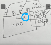
As shown in the schematic above: LCRC (B+ to power tubes) RC x2 (to driver/input tubes).
The extra RC per channel gives you extra channel separation.
Looks good! I can run new sims tomorrow.
So this R is the 600 ohm resistor?That is R1 10uF cap with 4x10k greenies across it.
View attachment 1228965
Physically i drew this from the PSU hardware received
View attachment 1228966
Attachments
In this amp's case, yes.It's almost greek to me. The second two V+ after the RCx2 are going to two different tubes? So I don' get that. is it a left and a right?
https://a-direct-heating-triode.blogspot.com/2022/11/gec-da41-se-a2-amplifier-part-2.html?m=1
There are 5 tubes on that amp. One is shared between both channels.

That means Red Wire 🙂 BK is black. BL is blue.So this R is the 600 ohm resistor?
The four squares are 10k resistors - the army green ones....
@Thekak Here is an article by a well known Frenchman (Rinaldo Bassi) that my friend shared with me on why choke input PSUs rule. You guys may understand it. I have made a rough translation under the article. I have a French background and it's my first language (many moons ago), but the tech terms are always hard to figure out. Maybe another Frenchie can improve my translation. Sharing this that was shared with me is helping me to take it in, maybe understand it better myself. I hope it sinks in one day.
The pictures are a bit fuzzy.

Figure 8
In choke input, thanks to the “coil/inductor”? there are no more transitory spike currents, not in the transformer nor in the rectifiers and the angle of conduction is 180’ . On the other hand the outgoing effective voltage is reduced to 0.9 of the incoming voltage.
L: choke/inductance coils
r: resistance of coils
C: capacitor
Figure 9a
Top:
Filter with a 2H coil and a 100uf capacitor. Depicting rectified and filtered current from point B in figure 8. about 180mA.
Practically represents a true sinus wave after filtration. Vcc = 0.6 V sinus.
Bottom:
Filtering with a capacitor - reserve is "as much as"??? 100uf - same current producing a 5Vcc saw wave.
Figure 9b
Top:
Filtering with a coil of 2H with current of 180mA consumed by the circuit.
Bottom:
Filtering with 100uF capacitor.
Current consumed by circuit of 180mA and peaks of current in the transformer and rectifiers of 425mA.
The pictures are a bit fuzzy.
Figure 8
In choke input, thanks to the “coil/inductor”? there are no more transitory spike currents, not in the transformer nor in the rectifiers and the angle of conduction is 180’ . On the other hand the outgoing effective voltage is reduced to 0.9 of the incoming voltage.
L: choke/inductance coils
r: resistance of coils
C: capacitor
Figure 9a
Top:
Filter with a 2H coil and a 100uf capacitor. Depicting rectified and filtered current from point B in figure 8. about 180mA.
Practically represents a true sinus wave after filtration. Vcc = 0.6 V sinus.
Bottom:
Filtering with a capacitor - reserve is "as much as"??? 100uf - same current producing a 5Vcc saw wave.
Figure 9b
Top:
Filtering with a coil of 2H with current of 180mA consumed by the circuit.
Bottom:
Filtering with 100uF capacitor.
Current consumed by circuit of 180mA and peaks of current in the transformer and rectifiers of 425mA.
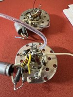
That whole diagram is just the power stage with the last wire coming out the B+ as it leaves the C1R1 network on its way to the cossor choke 2 in the PSU. The cossor is the 115ohm that is not yet hooked up as it will go on top of the left side of the amp beside tube - the big grey thing.So this R is the 600 ohm resistor?
The 600K one I have placed to replace the 5500k one in japanese circuit just before it goes into the OPT - TOP right half of schematic where the B+ comes up from the bottom. I can check an old socket i was given with resistors and caps on it to validate what that value should be. We need to get from 223 down to 160 after the OPT coil going into the plate of the 5687.
Each channel has three resistors and a cap. Here is the old signals tubes. In that installation there was one tube for each channel. Just using half of each tube.
I will measure the values this evening.

I will measure the values this evening.
Attachments
He's not planning on using a circuit like that, so I don't want to spend the time to simulate. I don't have time to review and figure out current draw and so forth on it. Sorry!Thekak
This is the original PSU ..
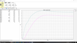
In PSU what does the sim. look like?
Yes I understand it isn't what fuse has at hand but it gives an approximation for intended purpose....
Okay, here's my attempt at using all the latest values. I've retained the 600 ohm resistor right before the 2nd choke (added 600 ohm to 115 ohm -> 715 ohm total resistance there).
This would represent a single independent RC arm for each channel, each with a 600 ohm resistor and an 8uF cap. I combine them together in PSUD.
I must be misunderstanding something as we are now down to ~100V B+. Otherwise it looks pretty good!.
If I remove the 600 Ohm resistor prior to the second choke, we will regain some voltage. Also if I lower the resistance for each RC section. But I'll wait for final measurements once again.
Attachments
Last edited:
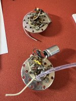
Here are the cap and resistors soldered to bottom of socket for one channel. I think the 300ohm and the 220uf are in my schematic to reduce the heater to 5.5??
But as you all know I have challenges with schematic vs how it’s actually wired. Ie where do caps and resistors soldered to bottom of socket appear on schematic and have we duplicated resistors as the voltage simulation is too low.

But as you all know I have challenges with schematic vs how it’s actually wired. Ie where do caps and resistors soldered to bottom of socket appear on schematic and have we duplicated resistors as the voltage simulation is too low.
Attachments
You just draw the schematic in a wrong way - there is nothing on heaters - i told You alredy - these elements are parts of the cathodes - the signs drawn on the schematic are wrong - I'll draw that part for You just give some time to do it and photograph it.Here are the cap and resistors soldered to bottom of socket for one channel. I think the 300ohm and the 220uf are in my schematic to reduce the heater to 5.5??
Here it is drawn fast
P.S. Normally / mostly as schematics are drawn - the heaters are not represented on picture of the triode.
P.P.S. Resistor & capacitor are in the cathode.
P.S. Normally / mostly as schematics are drawn - the heaters are not represented on picture of the triode.
P.P.S. Resistor & capacitor are in the cathode.
Attachments

Last edited:
Thanks so much @Thekak for doing this. Why does mine look different with same values?Okay, here's my attempt at using all the latest values. I've retained the 600 ohm resistor right before the 2nd choke (added 600 ohm to 115 ohm -> 715 ohm total resistance there).
This would represent a single independent RC arm for each channel, each with a 600 ohm resistor and an 8uF cap. I combine them together in PSUD.
I must be misunderstanding something as we are now down to ~100V B+. Otherwise it looks pretty good!.
If I remove the 600 Ohm resistor prior to the second choke, we will regain some voltage. Also if I lower the resistance for each RC section. But I'll wait for final measurements once again.
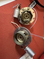
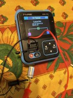
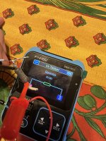
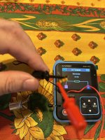
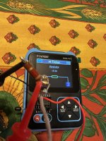
Same issue I had with the tutorials....the resistance of the secondary power transformer measured 71ohms. See picture from yesterday.
Look at the 6X5 datasheet - the transformer secondary resistance is probaby to low for 6X5 anodes - people are putting resistors in for each 6X5 plate when this is the case - the datasheet should tell You what is the minimum plate resistance for the tube so You can go on from there.
Correction the bumble bee one is 455. I must have forgot to press the test button.Here are the cap and resistors soldered to bottom of socket for one channel. I think the 300ohm and the 220uf are in my schematic to reduce the heater to 5.5??
But as you all know I have challenges with schematic vs how it’s actually wired. Ie where do caps and resistors soldered to bottom of socket appear on schematic and have we duplicated resistors as the voltage simulation is too low.

Look at the 6X5 datasheet - the transformer secondary resistance is probaby to low for 6X5 anodes - people are putting resistors in for each 6X5 plate when this is the case - the datasheet should tell You what is the minimum plate resistance for the tube so You can go on from there.
@krca45 Thank you. I will keep that in mind if I have issues. What would the symptom be for that?
Here is a picture of the PSU section working before sent to me. The LL2743 and the large 10uF cap are pictured and getting 223VDC off the C1 - V(C1) I guess......as it is wired right now....i need to put my heater transformer in the circuit that I tested yesterday and then figure out the signal chain to the signal tube.....I haven't fired it up yet as I just wired the small heater transformers yesterday. It was taking the heater before off the 6V secondary on the TRIO, but for my implementation split bobbin transformer was specified for the heaters...apparently that is better. So i will attach that in my test. I am not sure how to test it....whether the signal chain needs to be attached or whether i can just fire it up like this as well. First time i work with >120V so I am going to overthink it and be sure.
@krca
Last edited:
- Home
- Amplifiers
- Tubes / Valves
- "Serious Pre" Tube Build