After some planning the SEPTOR is on its way. It will be a rebuild of some old Erik Andersson(Audio Innovations, Audion etc.) 6B4G PPP monoblocks.
After the discussions in some other threads this is what came out.
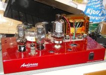
Note that the cathode resistor is substituted with a CCS. The toroid is a Talema with rewound secondaries. If the sims are right, as they usually are, there will be no problem to take out over 12W.
In the pic the KT66 is arranged instead of the EL519 as it is still in my warehouse.
After the discussions in some other threads this is what came out.
Note that the cathode resistor is substituted with a CCS. The toroid is a Talema with rewound secondaries. If the sims are right, as they usually are, there will be no problem to take out over 12W.
In the pic the KT66 is arranged instead of the EL519 as it is still in my warehouse.
An externally hosted image should be here but it was not working when we last tested it.
Attachments
Hi Lars
Looks interesting, very interesting actually. Just some questions:
1 - what CCS will you use for I1? Will a simple LM317 do?
2 - what is the size (capacitance) of C1?
3 - have you also simulated the distortion characteristics?
Succes with the built, I saved the thread for future reference (and experiments).
Erik
Hi Erik,
Did not add any component values as I hope someone else will also do some testing on their own. You could probably use a 317 but remember it is ca 45V over the CCS so a series resistor might be needed. The cap works like a parafeed so you have to do some experimenting.
Did not add any component values as I hope someone else will also do some testing on their own. You could probably use a 317 but remember it is ca 45V over the CCS so a series resistor might be needed. The cap works like a parafeed so you have to do some experimenting.
Have you looked into the "Wilson" 3 and 4 transistor current
mirrors? My early attempts with simplified 2 transistor mirrors
never quite seem to track each other with any linearity.
http://en.wikipedia.org/wiki/Wilson_current_source
You might also consider a parallel pair of IXCP10M45S, not
a true "mirror", but good and stable, very easy to match...
mirrors? My early attempts with simplified 2 transistor mirrors
never quite seem to track each other with any linearity.
http://en.wikipedia.org/wiki/Wilson_current_source
You might also consider a parallel pair of IXCP10M45S, not
a true "mirror", but good and stable, very easy to match...
Hi Lars
Thanks for your comments, I think I know enough for the moment. As said, the thread is saved and I have some PP iron that needs to be put to good use.
Kenpeter
That 4 transistor Wilson current mirror looks very interesting, but I did not quite understand if you compared the performance with the 2 transistor mirror? Did you? For me simple transistors work better, as the 10M45S costs more and needs to be sourced from a USA based shop.
Erik
In ALL my simple two transistor mirrors I've ever tried (maybe 4
attempts in total) unless an external sense resistor was used,
currents in the mirror branch do not linearly follow those of the
reference.
There's supposed to be intrinsic "Shockley" 26ohm impedance
to the emitter. And all bipolar transistors are supposed to be
the same in this regard. But in my experience, nobody seems
to have told any actual devices about this rule.
Obviously, the sand wizards that be have mastered this black
art for devices that share a common die (such as in op-amps).
Though they often end up abusing a Wilson anyway.
Linearity of followage in Wilson's 3 transistor variant may be
good enough, won't usually need any extra emitter resistors.
I'd use em anyway, just incase...
OPT balance will be in error by the amount of screen current.
I don't know if the amount we are talking is significant? To a
Toroidal type, maybe any error is significant... Taking screen
from the plate (through an RC low pass) ought to fix it.
I don't know if the amount we are talking is significant? To a
Toroidal type, maybe any error is significant... Taking screen
from the plate (through an RC low pass) ought to fix it.
How far the screen V drops will affect how much plate current it siphons off, of course. The usual horizontal output tubes with aligned grids spec out at 5 to 10%.
Putting an RC from plate to screen will just draw the AC screen current off to ground. (I'm assuming that's where Ken is connecting the cap.) What's needed is a HV Mosfet follower controlling the screen V with it's drain connected to the plate. (returning the current). Simplest of course would be to just use a Mosfet in the first place for the "anti-triode".
Don
Resistor from plate to screen, Cap from screen to ground.
Or optionally, from "center" of the screen resistor to GND.
Cap is what prevents becoming a simple triode strapping.
Holding screen voltage steady, just a little less than B+.
Even though the plate may regularly dip below this level.
Where else then can DC current come from, or go to?
Only from current source up to plate, where all then is
properly accounted for in the OPT. My last drawing
illustrates all three common strappings with cap to
detour the DC component through the full winding..
That drawing may have been in another thread...
When screen current bypasses the OPT, that was the
only error of DC balance I was suggesting to correct.
I don't see how Don's suggestion of FET with drain tied
to plate, holds the screen up when the plate dips? You
still need a cap in there somewhere...
---------------------------------------------------------------------
MOSFET is a good choice if you need the Anti-Triode to
faithfully fake pure parallel SE. But sand is certainly not
the only option that argues good sense.
Pentode blended may offer a very useful transfer curve
profile for an output stage. Nice and linear across the
middle, yet dissimilarly squashed on each end... I really
want to hear how this amp might sing at full volume.
Oh, OK. I follow you now. For some reason I was thinking AC current imbalance would be a problem too. Well, it would be if it causes distortion, ie non-linear screen current.
Hmmm, let's see, looks like the screen current increase (so pentode plate current decrease) at large signal level will sum with the triode side's increasing current draw at large signal level (non-linear effect). This will cause some signal envelope related current imbalance in the xfmr. Too bad the screen doesn't act the other way and cancel that problem instead of contributing to it.
Don
You are going to see the screen current at the cathode either way.
Its not a "problem" for triode strapping. Its not a "problem" for
UL strapping, and I see no reason its now suddenly a "problem"
for Pentode strapping? All thats really changed here: is that
long term DC balance can't leak around whatever limits the
current sources may have set. No big deal...
Its not a "problem" for triode strapping. Its not a "problem" for
UL strapping, and I see no reason its now suddenly a "problem"
for Pentode strapping? All thats really changed here: is that
long term DC balance can't leak around whatever limits the
current sources may have set. No big deal...
Yes, the cathode side of the pentode is matching the triode's current orders. But I was thinking about the LF balance of the xfmr with signal envelope, since the plate will be missing some current at high signal level (envelope related, ie LF effect).
Could use a floating screen supply (cathode to screen), so then screen current becomes irrelevant to everything.
Could use a floating screen supply (cathode to screen), so then screen current becomes irrelevant to everything.
Replace pentode with a cascode of two triodes. No screen to leak.
I just don't think its really necessary, the pentode works out fine.
The time constant for the screen can be well below anything you
or the reference triode will ever hear.
And suppose that RC constant it doesn't go down "all the way".
The primary mode of error will be to act a bit more like a Triode
instead of a Pentode, oh the horror!!!
AC-current imbalance before clipping will be in the ballpark of 10mA, at 6W ca 7mA. If it is of any significance listening tests will show.
Also did a quick sim with 2 parallelled 6AS7 in cascode and it seems to work even if sensitivity is lowered.
Also did a quick sim with 2 parallelled 6AS7 in cascode and it seems to work even if sensitivity is lowered.
You could probably use a 317 but remember it is ca 45V over the CCS so a series resistor might be needed.
Cascoding the 317 CCS might be a good idea as it could solve the voltage issue and improve the CCS bandwidth and impedance. Walt Jung shows some interesting examples in his recent audioexpress articles (on his WEB pages).
Hi Martin,
I´d rather prefer discrete sand, like a C4S styled currentsink.
kenpeter and Don,
The cascode seems to make even order distortion figures worse!
I´d rather prefer discrete sand, like a C4S styled currentsink.
kenpeter and Don,
The cascode seems to make even order distortion figures worse!
OK... Slight confusion here.
I referred to Don: a cascode as the Anti-Triode device, only as a
silly suggestion how one might get rid of Pentode screen current.
I think 6AS7 Cascode that Rev refs, is for the current source(s).
One per branch. Do I understand this correctly?
---------------------------------------------------------------------
Anyways, here's what I might do...
Take a reference voltage, like that red LED under the input
tube's cathode, low pass it through an RC, and bring it over
to set a fixed bias for the constant sand sources. Don't take
ref from the sand's own collector...
Now just scale the emitter resistors to set the currents.
Doesn't matter to cascode away all "Early" voltage on
the collectors. If the collector impedances aren't infinate,
its still a lot higher than a purely resistive tail for the
amount of cathode volts dropped.
There don't need to be any resistor or current source above
the collectors. I don't even know why that was put there...
Think you got it slightly wrong, kenpeter😉 !
I am grateful for the hint about the "leaking screen".
I have done some sims this afternoon showing promising figures with two cascoded triode-strapped EL519s instead of the pentode EL519. Works like a charm😀!
Have also done some sims with a cascoded 6080 in place of the 6P3S in the SETOR and it is also extremely promising.
About my currentsink combined with currentmirror (consisting of 4 transistors, 2 diode-strapped transistors and 2 LEDs) on the 6B4G it also seems to work fine. The configuration I have used is has a temperature drift between the anodes of ca 3mV, 25-100 degr. C. Actually you can see a slight difference in frequency response depending on configuration of CCS used. The resistor on the upper side of the ATs collector is to compensate for equal heat- contribution in the transistors.
Also remember any HF-loss in the triode-part is added when going AT. This together with the ripple sensitivety seems to be the downside of the circuit.
Gettin rid of ripple is easy, simply bypass/ultrapath output stage
screen and grid reference voltages up to B+. Then change input
triode out for a Pentode with an unbypassed cathode feedback
resistor and a screen voltage well bypassed to GND. The signal
at the input pentode's plate will then be common to B+ noise.
Same as the entire output stage, floating atop the twin constant
currents.
A cascode of triodes for anti-duty was, and is, completely silly.
Yes it would work, but at what supporting parts count? may
need higher B+, extra filament supply, and some sort of a
lowpass filtered midpoint ref.
Takes just as many R's and C's than to RCR a Pentode's
screen from the plate node. And no extra filament supply.
Lowpassing the screen's DC component to the plate will
completely correct the balance.
- Status
- Not open for further replies.
- Home
- Amplifiers
- Tubes / Valves
- SEPTOR AT-amp (Anti-Triode) being built