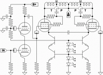
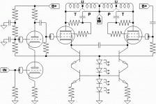
Totally wrong, kenpeter!To diss the cascode is as silly. No more parts needed than when decoupling the pentode. For the SEPTOR there is place for two EL519s. In the SETOR a 6080 will not take more space than a 6P3S.
Just give some time to try IRL Still waiting for toroids fot the SETOR-II. Guess they will be ready-built next week.
A pity we are so far apart, otherwise we could have a listening contest if you just built one your way 😎.
Just give some time to try IRL Still waiting for toroids fot the SETOR-II. Guess they will be ready-built next week.
A pity we are so far apart, otherwise we could have a listening contest if you just built one your way 😎.
I'd probably do a pair of 6CU5's in Triodlington/Pentodlington.
With independant 3way screen ref options for either branch.
If the transformer has no UL tap, there's ways to fake it.
I got a few too many 6CU5's at the moment.
With independant 3way screen ref options for either branch.
If the transformer has no UL tap, there's ways to fake it.
I got a few too many 6CU5's at the moment.
I like the idea of a cascode using a MOSFET below a triode-strapped
pentode. Or a triode, doesn't really matter but pentodes are cheap.
Something like a DN2540/EL86 would be a good match for a 2A3.
Michael
pentode. Or a triode, doesn't really matter but pentodes are cheap.
Something like a DN2540/EL86 would be a good match for a 2A3.
Michael
I don't see the point, except to look cool doing it?
What would be the purpose but to dissipate heat?
The MOSFET component would entirely control the
anti-sound (a pure slave to the reference triode).
Tube cascode above this does absolutely nothing
to or for the sound.
Plenty of sandy devices with high Gm needing no
cascode assistance in power or voltage depts.
Lean toward certain IGBTs as having the lowest
gate and reverse transfer capacitance to drive.
If I put any kind of tube on the Anti-side, it would
be to purposely engineer a custom blended curve.
There are good reasons to think that might be a
worthwhile experiment.
But not just to dissipate heat and voltage...
Waste of a good tube.
Reasons to use a tube vs. MOSFET
Lower capacitance. 7pF vs 50-150pF. Makes a difference in the
slew rate and slewing current. 250 uA for the tube, 2mA for the
50pF MOSFET at 20KHz and 565V Pk-Pk.
Tubes cool themselves through convection.
Easier to dissipate 15 watts at 100C vs trying to keep a
MOSFET case temperature below 50-60C for SOA and
reliability. No big heatsink required, just a little air flow.
Surge voltage tolerance. MOSFETs have very little tolerance for
anything and no sense of humor.
Reliability. MOSFETS have no sense of humor. Especially at high
voltage.
Cheers,
Michael
Lower capacitance to what? Its a cascode fer cripesake!
Grid totally bypassed to one rail or the other... You seem
happy to abuse a MOSFET underneath, where that gate
could potentially choose to be driven by a music signal.
(One of the easiest ways to wag the Triode into A2...)
If you find no humor in the odor of 600V MOSFRIED, you
may need to upgrade your technology. IGBTs withstand
1200V + before the magic blue smoke leaks out.
Again, gratuitous waste of good tubage, throwing one
at a power waster circuit where it exhibits no influence.
Even a rectifier tube does more to justify its existance.
I am by no means able to speak about the merits of mosfets X tubes as the anti-triode element, but I see some use for the GU50's (russian pentode, 40W dissipation that I bought at about 2 euros the piece) instead of the EL/PL519 in the septor.
Erik
Erik
I thought about adding a few more LEDs and biasing such that A2
was possible (mostly for the triode), but I'd have had to add one
more transistor to assure any grid currents returned to the plate.
And then I thought about cathode volt cost. Perhaps not worth A2
in a wag the dog topology. Not unless output tubes were already
pushed to the maximum plate or screen voltage they could safely
withstand, and you couldn't live another day without that one or
two extra watts.... The amp that cranks to 13.
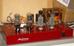
Attachments
GU50 needs a LOT of plate volts... Otherwise be prepared to drive
some currents into the grid and/or screen if 40W is to be realized
at the sort of voltages you are likely to feel safe in the same room.
If you do this with a torroidal transformer requiring full accounting
of all grid and screen currents return to the plate, you'll need some
extra drive Transistor or Triode (wired as a follower) to insure that
happens.
I have one here on loan with the tank it came from (meaning only
the original socket of course), I've posted xrays of the internals in
another recent thread.
kenpeter said:Lower capacitance to what? Its a cascode fer cripesake!
Grid totally bypassed to one rail or the other... You seem
happy to abuse a MOSFET underneath, where that gate
could potentially choose to be driven by a music signal.
(One of the easiest ways to wag the Triode into A2...)
If you find no humor in the odor of 600V MOSFRIED, you
may need to upgrade your technology. IGBTs withstand
1200V + before the magic blue smoke leaks out.
Again, gratuitous waste of good tubage, throwing one
at a power waster circuit where it exhibits no influence.
Even a rectifier tube does more to justify its existance.
The Coss of the top MOSFET in AT cascode is in parallel with the
OPT primary (AT side only). It can be balanced by adding a cap
to the triode side, it can be neutralized, or it can be reduced by
using a vacuum tube instead of the MOSFET. By my estimates,
the Coss of a MOSFET is significant in this circuit.
Some low voltage MOSFETs have low Coss but by the time
you get to the 800-900V devices that tend to be more
reliable, the Coss is up > 50 pF. What's the capacitance of
an IGBT?
How do you mean it exhibits no influence? It doesn't color the sound
but maybe that's a good thing if the MOSFET Coss is an issue. How
is the anti-triode a power waster circuit?
The heater power for an EL86 is less than 5 watts, less than
another 2A3.
GU50? would be good with a super 300B like the JJ, that also
handles 40 watts. With this combo you could push over 25 watts
in class A1.
Michael
IXGH 6N170A
http://ixdev.ixys.com/DataSheet/98989.pdf
23pF @ 1MHz Coes for the 1700V 75W part.
TO 247, fully insulated, with no screw hole.
Mind you, any error that tries to leak on account
of Coes will be fought tooth and nail by the Gm,
which is only a measly 3.5 Siemens! Comparable
to 3,500,000 uMhos in hollow terms.
Only the collector end will see the capacitive effect,
as-if to ground (or whatever other gate reference
the emitter end might be rigidly following).
2 buck 36 cent at Digikey 5 minutes ago...
But you'd have to order a minimum of 150, as
they haven't yet stocked up on this new part.
The quantity thing seems to be the deal killer.
Yet 600 Volters already cheap and plentiful.
And 1200V IGBTs are gettin there fast too.
--------------------------------------------------
If you ever look at the "Triode Region" of an
IGBT, it looks very-very triodish. More so than
any FET. But the Mu is near zero, so its kinda
useless except as a variable "plate resistor"
in SE Diode style of emulator.
You're right Michael, 23pF may be significant.
Into a 10k output impedance, you might see
a 3dB roll off (caused by Coes) at 692,329Hz.
I just couldn't live with that.
Into a 10k output impedance, you might see
a 3dB roll off (caused by Coes) at 692,329Hz.
I just couldn't live with that.
RDH4 gives some info on OT primary distributed capacitance on pages 226-227. 500 pF looks ball-park for no vertical sectioning (most OTs), while 2 vertical sections cuts that by 1/4 (better OTs). I was looking at these figures a while back when evaluating the switched capacitor impedance converter ( more like 100 pF).
The random wound toroid power xfmrs (120V:120V) are likely in the 10,000 to 20,000 pF or so range (and not even that much impedance ratio) due to the two HV windings being wound sorta bi-filar random. Non bi-filar primaries might be more like 1000 pF.
George mentioned some 240V toroid isolation xfmrs which would be much better. Would be nice to get some winding to winding cap. data on one of them. I haven't found one yet to buy.
Don
kenpeter said:You're right Michael, 23pF may be significant.
Into a 10k output impedance, you might see
a 3dB roll off (caused by Coes) at 692,329Hz.
I just couldn't live with that.
Oh I guess you must have golden ears after all ;-)
OK, the IGBT looks like a really good part. My concerns
were that the smallest HV MOSFETS in TO-247 packages
are 7N90 that have 160-180pF Coss. That's about 10%
power loss at 20KHz assuming mirroring a 300B with 5K,
but when summed with the triode side it's only 5%, which
is after all less than 1/2 db. Capacitance is
23pF is great; the 6N170 IGBT looks great overall for
up to maybe 25 watts after derating for a 1-2C/Watt
heatsink (which is still a big heatsink).
Maybe I can get some samples of the 6N170 to try to
blow up.
Michael
smoking-amp said:RDH4 gives some info on OT primary distributed capacitance on pages 226-227. 500 pF looks ball-park for no vertical sectioning (most OTs), while 2 vertical sections cuts that by 1/4 (better OTs). I was looking at these figures a while back when evaluating the switched capacitor impedance converter ( more like 100 pF).
The random wound toroid power xfmrs (120V:120V) are likely in the 10,000 to 20,000 pF or so range (and not even that much impedance ratio) due to the two HV windings being wound sorta bi-filar random. Non bi-filar primaries might be more like 1000 pF.
George mentioned some 240V toroid isolation xfmrs which would be much better. Would be nice to get some winding to winding cap. data on one of them. I haven't found one yet to buy.
Don
Hmm
Maybe I need to double check my calculations to see if I'm over
estimating the capacitive reactance and slew current. 500pF would
put 16K reactance in parallel with the anode load at 20 KHz.
In the 300B/5K case the effective Zpri will go from 5K to 3.8K
at 20 KHz.
I was basically trying to eliminate or at least marginalize the effect
of the extra Coss but maybe it's not worth worrying about at the
150pF level. That would be good news.
Thanks,
Michael
The sand discussion seems to be time-consuming, build and try IRL instead! Tubes are easiser to deal with. Can not afford heatsinks anyway😉.
I will try with cascoded EL519s anyway. Compared 1*EL519 pentode vs. 2*EL519 cascode in a few sims. Figures are very much alike except that second harmonic is diminished in the cascode case.
Have also tried a few double current-sources and they do not seem to be to critical but I go for a double C4S-style. Will absolutely not go for 317s or MOSFET.
A small heatsink to carry the CCSs will be placed over the novalsocket hole in the middle. The "OPT" will be placed inside the chassi.
Attachments
- Status
- Not open for further replies.
- Home
- Amplifiers
- Tubes / Valves
- SEPTOR AT-amp (Anti-Triode) being built