Very nice! Interested to hear what you think after you’ve spent some time with it
Thanks Cody! I’ve had it on all night burning in the amp. I’ll check the bias and offset again and start listening.
I used 0.22 ohm source resistors in the upper and lower positions and had R27 set at the recommended 68k ohms. When I powered up the amp bias was slightly over 500mv. I quickly lowered the bias to 400mv as I’m only using a 4U/300 chassis.
You have 2 output stage transistors and 0.8A Iq per board?
You have 2 output stage transistors and 0.8A Iq per board?
Hi RainFall, I have one IRFP240 in the CCS, and one SemiSouth in the output as per CodyT’s schematic. The only difference is that I have C5 as 5pf because I ordered as per the original BOM instead of the 10pf suggested my Cody.
Attachments

So you have 400mA bias per output transistor like you would do to store board with 4 output transistors.
Curren would be equally split per each output transistor.
Which means you have total 0.8A per channel (board).
Cody had 1.7A per board and increased later to 1.8A (850-900mA per output transistor)
Curren would be equally split per each output transistor.
Which means you have total 0.8A per channel (board).
Cody had 1.7A per board and increased later to 1.8A (850-900mA per output transistor)
Perhaps I misread things but I thought JSA1971 had 400mV across the 0.22R source resistor, which would be ~1.8A.
So you have 400mA bias per output transistor like you would do to store board with 4 output transistors.
Curren would be equally split per each output transistor.
Which means you have total 0.8A per channel (board).
Cody had 1.7A per board and increased later to 1.8A (850-900mA per output transistor)
Hi Rainfall, admittedly I’m not as advanced a builder as some others on this forum. So in relatively novice terms and explanations, I have R18 (0.22ohm as per one of CodyT’s suggestions) set at 400mv as per the original Aleph J build instructions, my heat syncs are sitting at 51 deg C in an ambient room temperature of 22 Deg C. Are you suggesting that I need to further increase the bias on R18? I’m fairly confident that would cook the transistors. Bare in mind that I’m going on the suggestion from Cody that an existing Aleph J build can be converted “without parts substitutions and still work well” with one SemiSouth and one IRFP240 and still work as intended.
Please help me understand what measurements I should have, and what I may not be understanding. And please be gentle 🙂
Are you suggesting that I need to further increase the bias on R18?
No. Dennis is right and I am wrong. Sorry for yet another misleading..
Please proceed with what you have.
.400/.22 = 1.81A sounds right to me. Just keep an eye on your temps, as you’re probably right at the acceptable threshold (I know I was)
.400/.22 = 1.81A sounds right to me. Just keep an eye on your temps, as you’re probably right at the acceptable threshold (I know I was)
Thanks Cody, will do. Temps on the sinks are steady at around 51 now with the bias holding around 400mv. I may back it off to 390 if I see it climbing higher.
Listening impressions so far are pretty on the mark with what you’d mentioned. More meaty on the lower to mid bass is what I’m finding so far, highs seem more Chrystal if that makes sense. I have found it a little less of the midrange I’ve come to expect with my current Aleph J. But then again, this one hasn’t really broken in yet so we shall see. Over all very pleased.
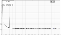
Was fooling around with the load/line on my newest AJSS boards today. I wanted to make another attempt at no degeneration on the Semisouth output device. Got a really nice result with .1R on top and 1A6 Iq (just in time for summer 😀). Nice and easy this time around with the 'Aleph pot,' and I'd estimate the AC gain resistance (R24 on store boards) to be around 1.8K.
Increasing the AC gain resistance is necessary due to the additional current coming from the top half after reducing its source resistance (itself necessary to feed the current-hungry SS running with no brakes.) Decreasing this resistance will bring your distortion down an arbitrary amount, but I like to target around .03% thd and maintain an overall AC gain from the modulated CCS of around 50%.
After basking in the glow of the Sony DIY VFET SE amp for a week, I was worried the AJSS would lose its luster. Not so 🙂
Attachments
.400/.22 = 1.81A sounds right to me. Just keep an eye on your temps, as you’re probably right at the acceptable threshold (I know I was)
So after letting the amp settle in and run for 2 days straight my bias had increased slightly to 402mv and the heat sync temps were at 52.5 Deg C with an infrared thermometer, and Nelson’s hand test method definitely revealed them feeling somewhere between Crikey & Bloody Hot.
I lowered the bias to 378mv which put them at 1.7A as suggested. I actually think the amp sounds better at that setting as well.
Interesting to note is that the bias across R18 actually went down a little with the lid on after adjustment. Anyone have an explanation they may share?
Yes, the Semisouth devices have a negative temperature coefficient. One of their many benefits 🙂
without look at actual schm, me no habla español
🙂
Lol, ZenMod me neither, “some” Italian is all I can muster outside of English.
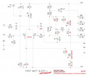
Here’s the schematic as published by CodyT, and the one I worked of off. In my build both R18 & R16 are .22ohm, with Iq now at 1.7A. Previously at approx 1.8A
Attachments
Yes, the Semisouth devices have a negative temperature coefficient. One of their many benefits 🙂
Very cool and interesting. Any literature you can pass on for me to read?
Before you point out that bias arrangement, just know that the schematic is made to approximate a conversion from the store boards. 🙂
Very cool and interesting. Any literature you can pass on for me to read?
The data sheet is the only thing I can think of: http://www.farnell.com/datasheets/1464473.pdf
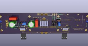
V3 inspired by Cody AJ SS. 🙂
AJ hybrid with J2 LTP and BA1/BA2 CCS.. 😀
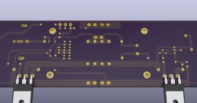
P.S.: Already found some trace error while moving some parts. Already fixed if you will see it. )
AJ hybrid with J2 LTP and BA1/BA2 CCS.. 😀
P.S.: Already found some trace error while moving some parts. Already fixed if you will see it. )
Attachments

Last edited:
V3 inspired by Cody AJ SS. 🙂
AJ hybrid with J2 LTP and BA1/BA2 CCS.. 😀
P.S.: Already found some trace error while moving some parts. Already fixed if you will see it. )
Really like the clean layout, well done.
- Home
- Amplifiers
- Pass Labs
- Semisouth Aleph J?