Resistor reduction reduces distortions on high frequencies?NO, this will only increase delay in PWM signal...
DT (dead time) can be only slightly corrected by gate resistors...
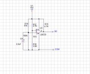
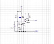
I have committed this error at drawing, in the scheme at me as in your correction.I have found one error in the shematics. This can even destroy the driver if the power supply will be applied too fast... Please see the image.
I am wondering, that no one have seen it before... 🙁
I have committed this error at drawing, in the scheme at me as in your correction.
Ok good! 🙂
A supply voltage now +/-65V to measure frequency there is nothing, the amplifier works stably on an input tl081, there was only a small impulse at deenergizing.is stable amplifier? (2x80V)
frequency?
What is still missing?
with tl81?
amplifier must complete and they work with any PSU.
this is the right way to solve all the necessary serving on a good amplifier.
disable the driver is correct (when the voltage starts to fall)
Now put a comparator which controls the voltage (there are many ways of course)
this is the right way to solve all the necessary serving on a good amplifier.
disable the driver is correct (when the voltage starts to fall)
Now put a comparator which controls the voltage (there are many ways of course)
Resistor reduction reduces distortions on high frequencies?
Not always 🙂 This affects the dead time. Reducing gate resistors, DT will be reduced also. For distortions it is important that the DT is as small as possible, but it is more important to avoid shoot through.
this circuitis lock only voltage drop.
indipendent from vc (10-15V).
tell me if you have also necessity of delay when enable SD.
Yeah, this will generate SD signal also when the power supply will sag under load 😀
And if the PSU will discharge slowly, then this scheme will not generate any SD signal... 🙄
But overall idea is very good! 😉
Last edited:
To 81bas.
You have developped amplifier for you?
...tells🙂
Look at your post #21 first... 🙄 The amp is working now, ask Vogor 😉
I have not developed any commercial class D amp, it is not my target. I am a programmer and electornics is only my hobby, but I understand some things and I try to help others in this forum to solve the problems, which I have solved previously...
If a little to reduce R13 (6,8K), for example to 4,7K that distortions should decrease and what with efficiency it will grow?Not always 🙂 This affects the dead time. Reducing gate resistors, DT will be reduced also. For distortions it is important that the DT is as small as possible, but it is more important to avoid shoot through.
if it is too small that there will be a through current?
This scheme is a bit more difficult published in a post 68 on one transistor, what than advantage at it? It also makes signal SD for driver closing at decrease in a supply voltage and eliminates "a deenergizing impulse" what at it an operation threshold, V1 (13V) whence it is necessary to submit? Whether it is possible to replace lm339 on lm311?treshold difference is damping.
driver voltage not decrease significative at power.🙂
Hi,
Yes, can replace with LM311 (this is only faster).
Cut-Off is Independent from Vcc.
function is immediately disable SD.
my help is difficult without your schematic.
If you put on this thread, I can control everything.
Yes, can replace with LM311 (this is only faster).
Cut-Off is Independent from Vcc.
function is immediately disable SD.
my help is difficult without your schematic.
If you put on this thread, I can control everything.
If a little to reduce R13 (6,8K), for example to 4,7K that distortions should decrease and what with efficiency it will grow?
R13 is NOT a gate resistor 🙂 Gate resistors in your schematic are R15 and R16. But I would not change them... 🙄
if it is too small that there will be a through current?
Yes
- Status
- Not open for further replies.
- Home
- Amplifiers
- Class D
- Self-oscillating class D amplifier

