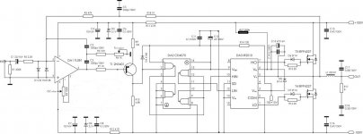
It is needed to play on R4 and R2. But 35-40V threshold is OK too, I think... 🙄
Thanks! 🙂
thank's AP2, like this?
How about sound quality compare to IRS2092 based amp?
Hi,
it is good for start D class,to learn about the various problems.
I do not like IRS2092 amplifier and this scheme is too slow for my taste.🙂
certain works.
regards
it is good for start D class,to learn about the various problems.
I do not like IRS2092 amplifier and this scheme is too slow for my taste.🙂
certain works.
regards
i never tried aCD 4070, but a CD4049 gives outstanding results as a comparator
I get 1.3mhz self oscillation
I get 1.3mhz self oscillation
This is why the startup circuit on T2 was here 😉
Measure a voltage on C13 when the amp is 'not working' (before giving input signal). If it is less than 8-10 volts, then it is needed to reduce the resistor between Vb and +65V. Also, if the resistor is too small, then it can produce too high voltage on C13 and damage the driver. To be safe, simply put a 15V Zener diode (стабилитрон) parallel to C13.
Also, if this will not help, then it will be needed to insert delayed SD signal for IR2110.
Hi ,I have try as your suggestion . But there is 15VDC offset on out output also and amp did not start. Why?
I have only blown my output stage once with an high supply voltage around 190V (and 13200uF of low ESR caps). I was doing power testing and I was in another room with two closed doors and two concrete walls inbetween, yet I could hear the bang in detail.
The result was a lot of vapourized PCB (thick polygons, not just tracks), exploded TO-220 cases, vapourized TO-220 leads, and some small SMD parts disappeared.
And this happened with a quite mature design, not just the first prototype.
In other words, be careful 😉
btw: Your design lacks many important things.
btw2: An high-speed op amp can't do the work as a hi speed comparator, and vice-versa. A comparator is a one bit analog to digital converter. An op-amp is intended to produce an analog output. Comparators exhibit very high gain and slew rates at the expense of the inability to make them work in a NFB loop. 5mV of overdrive are enough to change the state of the outputs completely within a few dozen nanoseconds.
Did you ever hear a welding inverter blow? 5 Kw version smps I was working on, with big igbt, always be carefull and use a limiter in powerlines as I do now.
These things shall happen once. Upon that failure I developed a simple system that detects a short in output stage, shutting down gate drive within 1us. No more meltdowns. Once, while testing said prototype in a party, it got some mechanical damage while I was not present. One output MOSFET lost gate contact and blew. The amplifier worked again after cutting out the damaged MOSFET (the design uses pairs of TO-220). The party continued till end.
Hi,
My post "LM339" circuit solved two problems.
startup and no"PUP" when switch-off psu.
You have tested?
Good afternoon. I did not find this post.
You can send me: luizcpimenta@gmail.com
- Status
- Not open for further replies.
- Home
- Amplifiers
- Class D
- Self-oscillating class D amplifier

