After the resistor I did not put the condenser, did not assume such effect... It was necessarily necessary? What for stabilizer fluctuations? Yes also top mosfet has burnt down. Whether there can be still any reason of an event?Oh, it is very bad news 🙁
Was there any capacitor before 7812 after 4.7K resistor? 7812 can very often start to oscillate...
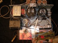
Please, post your final blown scheme here (with all connections of startup/shutdown PCB, with 7812 connections, etc), we will try to find the reason. I think the output mosfets are blown too 🙁
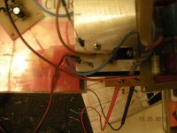
Attachments
I have simply decided to test once again the scheme which have offered 81bas, I did not assume explosion of details...Hi,
you like to complicate life.😕
Then you also do the protections of current, lm-circuit also has input shunt-down.(re-start right)
lose more time like that.🙂
Hi Vogor,
Is correct use +18V (not from power-vcc) for 7812.
big cap before 7812is ok, after (7812) use small max 10uF+100nF near to pin-out.
Is correct use +18V (not from power-vcc) for 7812.
big cap before 7812is ok, after (7812) use small max 10uF+100nF near to pin-out.
After the resistor I did not put the condenser, did not assume such effect... It was necessarily necessary? What for stabilizer fluctuations? Yes also top mosfet has burnt down. Whether there can be still any reason of an event?
Did you started your amp without any heatsinks??? 😱 At +/-65V rails even at idle the output mosfets will overheat very quickly!
Also, at startup IR2110 consumes very low current, and there was not enough voltage drop on 4.7K, so 7812 was still powered with about 60V at least, giving about 30-40V at output 🙄 So it was not very good idea to use 4.7K resistor to GND 🙁 It was very simplier to disconnect the fans temporarily, to test the functionality 😱
How you represented the driver Vcc is derived from -65V rail via 7812 stabilizer except as through the resistor? Without amplifier connection your scheme of start/deenergizing worked.And as I said, 7812 is not intended to work at 65V (even via some resistor). Also, was the 4.7K resistor blown too?
How you represented the driver Vcc is derived from -65V rail via 7812 stabilizer except as through the resistor? Without amplifier connection your scheme of start/deenergizing worked.
I did not recommend to do such connection at all! I was thinking previously, that it is connected in such way, but I was wrong. 🙄
My scheme cannot blow any IR2110, so the reason is either you started your amp without heatsinks or 7812 gave too much output voltage from unknown reason (because of oscillation, for example)...
Last edited:
It agree, in pulse devices to save to itself more expensively.Hi Vogor,
Is correct use +18V (not from power-vcc) for 7812.
big cap before 7812is ok, after (7812) use small max 10uF+100nF near to pin-out.
The amplifier worked stably and without heatsinks, the unique reason which is possible this formation of parasitic communication through a PSU, explosion has shown that for your scheme of deenergizing the obligatory external stabilizer for 7812 is necessary. You wrote that probably fluctuation 7812 it that for effect, you already saw such?I did not recommend to do such connection at all! I was thinking previously, that it is connected in such way, but I was wrong. 🙄
My scheme cannot blow any IR2110, so the reason is either you started your amp without heatsinks or 7812 gave too much output voltage from unknown reason (because of oscillation, for example)...
You wrote that probably fluctuation 7812 it that for effect, you already saw such?
Yes, I have seen oscillating 78XX very often. They can even heat from such reason, when there is nothing connected to the output! 😀
For my startup/shutdown schematic is important, that the driver vcc will fall down AFTER the main power supply. Disconnecting the fans from your 18V supply would provide this effect easily.
The amplifier worked stably and without heatsinks
are you sure, that the amp was started in this case? you wrote, that it was needed to give some small input signal, before it starts to work 🙄
Ok, I will continue experiments later.Yes, I have seen oscillating 78XX very often. They can even heat from such reason, when there is nothing connected to the output! 😀
For my startup/shutdown schematic is important, that the driver vcc will fall down AFTER the main power supply. Disconnecting the fans from your 18V supply would provide this effect easily.
are you sure, that the amp was started in this case? you wrote, that it was needed to give some small input signal, before it starts to work 🙄
I have reduced 200K the resistor to 100K now with it everything is all right 🙂
I have reduced 200K the resistor to 100K now with it everything is all right 🙂
Then why you needed the startup/shutdown circuit at all? Only because of small PUP at shutdown?? 🙂
Yes, I wish to eliminate this PUP at shutdown, then still protection and a limiter will need to be added 🙄Then why you needed the startup/shutdown circuit at all? Only because of small PUP at shutdown?? 🙂
I have reduced 200K the resistor to 100K now with it everything is all right 🙂
Also, did you used the Zener diode parallel to C13? With 100K resistor at driver idle there can be produced too high voltage also!
Also, I think I understand the reason of this failure... In my startup/shutdown schematic I have seen in simulations, that the 100uf cap will charge to 15V in 2-3 seconds via 100K resistor (providing SD delay) with 65V rails, and if you connected my startup/shutdown circuit, then it has produced the startup delay, and your 47uf C13 cap have charged via 100k resistor in 2-3 seconds to about 30 Volts!!! (at idle the driver consumes very small current) Sure it has killed your upper mosfet after startup! And I have recommended you to use the Zener diode parallel to C13 already in previous posts! 😉
Then why you needed the startup/shutdown circuit at all? Only because of small PUP at shutdown?? 🙂
LOL! I have seen in IR2110 datasheet now, that after active SD, the high and low side will be NOT reenabled, if the HIN or LIN is active 😀 So delaying the SD signal at startup will not help to start amp oscillation! 😀 (have AP2 said about it already?)
Also, connecting the 100K resistor between +65V and the amp OUTPUT will help to start oscillation in the same way, as connecting this resistor to Vb! 🙄 It works because 100K resistor produces POSITIVE DC offset at output during startup (via charging C13 or directly) and the input integrator needs to initiate the oscillation with NEGATIVE pulse 😀
Shame on me, that I did not realised it previously 😀
Last edited:
Yes, similar top mosfet has burnt down for this reason, zener in parallel с13 could rescue the scheme... So what your general result taking into account result of my last experience? your scheme of deenergizing will work if to use the separate rectifier for 7812?LOL!...
Shame on me, that I did not realised it previously 😀
Yes, similar top mosfet has burnt down for this reason, zener in parallel с13 could rescue the scheme... So what your general result taking into account result of my last experience? your scheme of deenergizing will work if to use the separate rectifier for 7812?
yes, this will work! 🙂 The startup delay seems to be useless, but since you have implemented this already, it will not interfere. 😉
One more moment, what elements in your scheme are responsible for operation and occurrence SD border, at amplifier "PUP" deenergizing appeared almost at once, I think it is necessary to raise a threshold to 55V, what it is necessary to change for this purpose?yes, this will work! 🙂 The startup delay seems to be useless, but since you have implemented this already, it will not interfere. 😉
One more moment, what elements in your scheme are responsible for operation and occurrence SD border, at amplifier "PUP" deenergizing appeared almost at once, I think it is necessary to raise a threshold to 55V, what it is necessary to change for this purpose?
It is needed to play on R4 and R2. But 35-40V threshold is OK too, I think... 🙄
- Status
- Not open for further replies.
- Home
- Amplifiers
- Class D
- Self-oscillating class D amplifier